Vimar ELVOX 6680/V03 Handleiding
Vimar
Niet gecategoriseerd
ELVOX 6680/V03
Bekijk gratis de handleiding van Vimar ELVOX 6680/V03 (40 pagina’s), behorend tot de categorie Niet gecategoriseerd. Deze gids werd als nuttig beoordeeld door 46 mensen en kreeg gemiddeld 4.9 sterren uit 23.5 reviews. Heb je een vraag over Vimar ELVOX 6680/V03 of wil je andere gebruikers van dit product iets vragen? Stel een vraag
Pagina 1/40

TYPE 6680
Cod. S6I.668.00E RL.13 5/2012
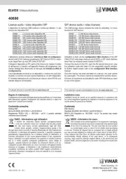
POWER SUPPLY FOR SINGLE AND MULTI-RESIDENTIAL VIDEO DOOR ENTRY SYSTEMS WITH “SOUND SYSTEM”
CALL
GB
INSTALLATION AND OPERATION MANUAL
Product is according to CE mark and directives:
- EC Directives 2004/108/CE and following norms.
- EC Directives 2006/95/CE (73/23/CEE) and following norms.
Power supplies constitute SELV sources in compliance with the requirements stipulated in Article 411.1.2.2 of CEI standard 64-8 (ed.
2003).
Production is subject to costant surveillance:
DVE

GB
6680
2/40
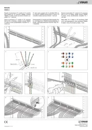
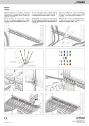
GENERAL RULES FOR INSTALLATION
Wiring should be installed in separate lines from electrical
and industrial cables. The use of coloured conductors will
facilitale connections. For the camera entrance panel instal-
lation, please, note that:
A) Camera operates from -5° + 50° C; to avoid overheating,
protected it from sunlight with some form of shelter.
B) Lens must be protected against direct light (sun, car hea-
dlights, etc.).
C) Person to be framed by camera must be illuminated from
the front. If lighting is insufficient use an additional exter-
nal lamp powered directly by the mains.
D) Before closing unit, clean protective glass and lens, re-
peat this operation from time to time.
Power supply type 6680 must be placed in a dry place far
from sources of dust and heat. To facilitate check-ups and
adjustments, make sure that the place is easily accessible.
Fix power supply to wall with proper support and fixing
screws provided with the package or inserting it with proper
DIN module. Before connecting it, ensure that conductors
are not interrupted or short-circuited.
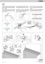
Installation should be made in lines separated from electric
mains. To ensure user safety, all units run on low voltage and
are separated from electric-mains by an high isolation tran-
sformer. It is advisable, in any case, to instal a thermal ma-
gnetic switch with an adequate capacity between the
supplying mains and the unit. When repairing and/or servi-
cing the power supply it will be sufficient to loosen the
screws placed on the front side to remove the front panel,
after having switched off the power.
SAFETY INSTRUCTIONS FOR INSTALLERS
- Carefully read the instructions on this leaflet: they give impor-
tant information on the safety, use and maintenance of the in-
stallation.
- After removing the packing, check the integrity of the set.
Packing components (plastic bags, expanded polystyrene
etc.) are dangerous for children. Installation must be carried
out according to national safety regulations.
- It is convenient to fit close to the supply voltage source a
proper bipolar type switch with 3 mm separation (minimum)
between contacts.
- Before connecting the set, ensure that the data on the label
correspond to those of the mains.
- Use this set only for the purposes designed, i.e.for electric
door-opener systems. Any other use may be dangerous. The
manufacturer is not responsible for damage caused by im-
proper, erroneous or irrational use.
- Before cleaning or maintenance, disconnect the set.
- In case of failure or faulty operation, disconnect the set and
do not open it.
- For repairs apply only to the technical assistance centre au-
thorized by the manufacturer.
- Safety may be compromised if these instructions are disre-
garded.
- Do not obstruct opening of ventilation or heat exit slots and
do not expose the set to dripping or sprinkling of water.
- Installers must ensure that manuals with the above instruc-
tions are left on connected units after installation, for users'
information.
- All items must only be used for the purposes designed.
- The ominipolar switch must be easily accessed.
WARNING: to avoid the possibility of hurting yourself, this unit
must be fixed to the wall according to the installation instructions.
- This leaflet must always be enclosed with the equipment.
Directive 2002/96/EC (WEEE)
The crossed-out wheelie bin symbol marked on the pro-
duct indicates that at the end of its useful life, the product
must be handled separately from household refuse and must
therefore be assigned to a differentiated collection centre for
electrical and electronic equipment or returned to the dealer
upon purchase of a new, equivalent item of equipment.
The user is responsible for assigning the equipment, at the end
of its life, to the appropriate collection facilities.
Suitable differentiated collection, for the purpose of subsequent
recycling of decommissioned equipment and environmentally
compatible treatment and disposal, helps prevent potential ne-
gative effects on health and the environment and promotes the
recycling of the materials of which the product is made. For fur-
ther details regarding the collection systems available, contact
your local waste disposal service or the shop from which the
equipment was purchased.
Risks connected to substances considered as dangerous
(WEEE).
According to the WEEE Directive, substances since long usually
used on electric and electronic appliances are considered dan-
gerous for people and the environment. The adequate differen-
tiated collection for the subsequent dispatch of the appliance for
the recycling, treatment and dismantling (compatible with the
environment) help to avoid possible negative effects on the en-
vironment and health and promote the recycling of material with
which the product is compound.

6680
3/40
GB
OPERATION
The video door entry installation consists of one camera entrance panel with speech unit, one power supply and one or more mo-
nitors. The system can operate with monitors and B/W or colour cameras and with or without conversation privacy.
The power supply is not equipped with intercommunicating section; nevertheless it is possible to set up a monitor and/or inter-
communicating interphones network using switching module type 935A in conjunction with the basic power supply.
When an entrance panel push-button is pressed, the ringtone rings in the corresponding apartment. Almost immediately the image
of the caller appears on the monitor. The coverage area is illuminated by built-in infrared leds when using B/W camera, or by a built-
in white light when using a colour camera.
If desired, the user may simply raise the interphone, communicate with the caller and, if appropriate, activate the door-opener. In
this case, door-opening time may be varied from 1 to 30 seconds using the potentiometer P3.
The system turns itself off automatically after a preset time, adjustable from 30 to 90 seconds using potentiometer P1 inside the
power supply. If the caller presses another user’s push-button, the previously called monitor is automatically disactivated without
waiting for the end of the preset time. When testing the installed system, use trimmer P2 to adjust the optimal volume of the spe-
ech unit. For simultaneous activation of two or more monitors one extra power supply type 6582 must be installed for each ad-
ditional monitor or type 6583 for more monitors. A blocking circuit cuts off power to monitors if the line is overloaded or
short-circuited. The power supply is also equipped with a specific device to eliminate any buzzing on the voice circuit caused by
the use of wires that are too long and/or too thin only in installations with “SOUND SYSTEM” call. Push-buttons with name-tags
are illuminated through output 0-15 on power supply. Up to a maximum number of three 24V 3W bulbs can be connected. An ad-
ditional transformer, type M832 or 0832/030 is required for entrance panels with more bulbs.
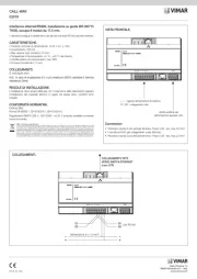
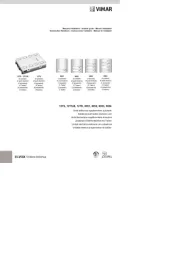
Technical specifications of power supply type 6680 - (6680/V03)
type 6680 is the basic power supply for all video door entry systems with SOUND SYSTEM call and is equipped with an electro-
nic double tone generator, which replaces conventional alternative calling with a buzzer or bell. The sound is emitted with two dif-
ferent tones (present on terminals C1-C2) thereby allowing the user to immediately identify the source of the call (main entrance,
gate, garage, etc.). This feature provides economic and practical advantages since the use of several conventional sound emit-
ting systems is no longer required; the signal is emitted from a single loudspeaker in the interphone. In some cases, savings can
be made on the cable routing work requirements for additional bell systems. Manufactured in copolymer class V-0 housing; pre-
set for mounting on cases with 12-Module DIN support or with expanding plugs with screws.
- 230V A.C. 50Hz supply (other voltages on request)
- 60VA maximum absorbed power.
- 18V D.C. 0.8A monitor supply. (90 sec. ON, 90 sec. OFF)
- 13V D.C. 0.3A camera supply. (90 sec. ON, 90 sec. OFF)
- 15V rectified voltage 0.25A continuous duty output for push- push-button illumination (3x24V 3W max)
- 15V A.C. 1A door lock output; intermittent service. (30 sec. ON, 150 sec. OFF)
- Amplified audio door entry system.
- Timer and automatic disconnection device of monitor previously activated.
- Interchangeable cards for quick maintenance.
- Removable terminal blocks.
POWER SUPPLY OPERATING MODES
- Selector set A-B:
- “A” Position: operating with sound system call, to be used in case of humming noises (caused by power supply, door lock or
lamps) dectected on the interphone line.
- “B” Position: normal operation with Sound System call, switching module in “A” position only in case of humming noises on the
audio line.
- “B” Position: operating with 15V A.C. call only. In this case power supply 6680 completely replaces power supply type 6580.
PROTECTION OF POWER SUPPLY:
- Primary coil of transformer by PTC
- 1st. secondary coil for internal electronic supply by F 3,15A 250V (F1) fuse.
- 2nd. secondary coil for lock supply by PTC
- Electronic protection against short-circuits and overloads on
monitor cable riser.
- Electronic protection against overloads to speech unit.
ADJUSTMENTS
P1 - Activation time adjustment for monitor and camera.
P2 - Volume adjustment of speech unit.
P3 - Activation time adjustment for electric lock.
N.B.: The electric door lock must operate by way of an intermittent cycle so that one
operating period corresponds to 5 rest periods, thereby preventing the protection
device from overheating (one period corresponds to the door lock activation time).
Dimensions type 6680 - 6680/V03: 208x135x72 - Weight: 1.4 Kgs.
Removable terminal blocks
Selector A-B
Product specificaties
| Merk: | Vimar |
| Categorie: | Niet gecategoriseerd |
| Model: | ELVOX 6680/V03 |
Heb je hulp nodig?
Als je hulp nodig hebt met Vimar ELVOX 6680/V03 stel dan hieronder een vraag en andere gebruikers zullen je antwoorden
Handleiding Niet gecategoriseerd Vimar
2 September 2025

26 Augustus 2025
26 Augustus 2025
26 Augustus 2025
14 Augustus 2025
5 Juli 2025
5 Juli 2025
5 Juli 2025

5 Juli 2025
24 Mei 2025
Handleiding Niet gecategoriseerd
- Silver Style
- Quik Lok
- ALC
- Sirius
- Exalux
- Belanger
- German Sport Guns
- ReTrak
- Fysic
- Auto Joe
- Matrix Audio
- Carson
- Mitsubishi
- Kaiser Nienhaus
- CMTECK
Nieuwste handleidingen voor Niet gecategoriseerd
15 September 2025

15 September 2025

15 September 2025

15 September 2025

15 September 2025
15 September 2025

15 September 2025
15 September 2025
15 September 2025

15 September 2025