Vimar 14529.120 Handleiding
Vimar
Niet gecategoriseerd
14529.120
Bekijk gratis de handleiding van Vimar 14529.120 (6 pagina’s), behorend tot de categorie Niet gecategoriseerd. Deze gids werd als nuttig beoordeeld door 46 mensen en kreeg gemiddeld 4.9 sterren uit 23.5 reviews. Heb je een vraag over Vimar 14529.120 of wil je andere gebruikers van dit product iets vragen? Stel een vraag
Pagina 1/6

L1 S L2
L
N
Bus
S S S
20529.120
19529.120
16969.120
14529.120
20137.120
19137.120
16604.120
14137.120
20137.120
19137.120
16604.120
14137.120
20416
19416
16460
14416
20416
19416
16460
14416
120
120
Viale Vicenza, 14 - 36063 Marostica VI Italy
Tel. +39 0424 488 600 - Fax (Italia) +39 0424 488 188 - Fax (Export) +39 0424 488 709
www.vimar.com
49400519A0 01 1309
VIMAR - Marostica - Italy
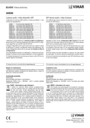
Apparecchio di comando a due pulsanti basculanti e attuatore per regolatori SLAVE
120 V~ 60 Hz, per lampade LED, trasformatori elettronici LED, lampade RGB, alimen-
tatori elettronici RGB, da completare con tasti intercambiabili 1 o 2 moduli - 2 moduli.
Il dispositivo non può controllare direttamente il carico. Va utilizzato come pulsante doppio o singolo a
seconda del tasto scelto. I pulsanti possono essere configurati anche indipendentemente dalla parte
di pilotaggio del regolatore SLAVE e possono essere premuti sia nella parte superiore che inferiore.
IMPORTANTE: Le lampade o gli alimentatori elettronici controllabili da un singolo apparec-
chio di comando devono essere tutti dello stesso tipo.
Non è possibile pilotare contemporaneamente con uno stesso apparecchio di comando a
due pulsanti basculanti sia LED bianchi che LED RGB.
CARATTERISTICHE.
• TensionenominaledialimentazioneBUSTP:29V
• Tensionenominaledialimentazionerete:120V~,60Hz
• AssorbimentodabusTP:13mA
• Tastiabbinabili:doppioo1singolo
• Morsetti: sincronismo,busTPL1 L2 S, ,
• Funzionirealizzabilidaitasti:
- interruttore ON/OFF
- comando per tapparelle
- comando per regolatore
- attivazione di 2 scenari
• Funzionirealizzabilidalregolatore:
- accensione, spegnimento e regolazione
-cambiocoloreassoluto
- regolazione tonalità/saturazione/luminosità
-funzionamentoFADING-SHOW
- modalità “flash start” per lampade CFL
- funzionamento “rampa”
- ritardo di disattivazione e funzionalità di “preavviso”
-tagliodifase:LE/TE
•Non compatibile con centrali By-me 2 moduli incasso (art. 20510, 16950 e 14510)
•La funzione RGB non è supportata dall’articolo 16969.120 della serie Idea
CONFIGURAZIONE.
PER LE OPERAZIONI DI INSTALLAZIONE E CONFIGURAZIONE, VEDERE IL MANUALE
ISTRUZIONI DEL SISTEMA By-me ALLEGATO ALLA CENTRALE DI CONTROLLO.
L’operazione di configurazione deve essere effettuata con il dispositivo privo di tasto per poter
premere il pulsante centrale di configurazione.
• Blocchifunzionali:3(2pulsanti, 1attuatoreregolatore),ognibloccofunzionalepuòapparte-
nere al massimo a 4 gruppi.
•Selezionedelbloccofunzionaleinfasediconfigurazione:
-premereilpulsantediconfigurazioneedattendere3sperselezionareilbloccofunzionaleregolatore;
- premere il pulsante di configurazione e successivamente il tasto desiderato per selezionare
ilrelativobloccofunzionalepulsante.
La configurazione inizia all’accensione del led rosso e termina con il suo spegnimento.
A dispositivo non configurato l’attuatore è comandato dal tasto sinistro.
•Se il dispositivodeve essere configurato come un pulsantedoppio è necessario premere il
tasto di sinistra.
Si consiglia di configurare il dispositivo a carico spento.
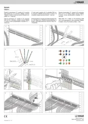
REGOLE DI INSTALLAZIONE.
L’installazione deve essere effettuata con l’osservanza delle disposizioni regolanti l’installazione del
materiale elettrico in vigore nel paese dove i prodotti sono installati.
•Vautilizzatoinluoghiasciuttienonpolverosiadunatemperaturacompresatra-5°Ce+45°C.
• Sovraccarichi, archi elettrici e cortocircuiti danneggiano irreparabilmente il regolatore. Prima
dell’installazione eseguire un’attenta verifica del circuito eliminando le eventuali cause sopra esposte.
• Il regolatore non è provvisto di interruzione meccanica nel circuito principale e non fornisce
quindi separazione galvanica. Il circuito sul lato carico deve essere considerato sempre in tensione.
•Perulterioriistruzionisivedailmanualeallegatoallacentraledicontrollo.
Carichi comandabili
N° max
20529.120
19529.120
14529.120
16969.120
Regolatori SLAVE
(20137.120-19137.120-16604.120-14137.120-01871.120)
3 3
Lampade
(02662.120 o 02663.120)
10 Non applicabile
Alimentatorielettroniciregolabili
(01874.120-01875.120)
10 10
AlimentatoreelettronicoRGBregolabile
(01876.120)
10 Non applicabile
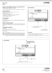
morsetti bus TP
VISTA FRONTALE E POSTERIORE
Pulsante di configurazione
LED L1 S L2
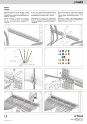
COLLEGAMENTO CON REGOLATORE SLAVE UNIVERSALE
L1 S L2
COLLEGAMENTO CON 01874.120-01875.120 E MODULO/STRISCIA LED
Lunghezzamassimadeicavidicollegamentotral’attuatoreperregolatoreelalampadaLEDdimmerabile
oalimentatorielettronicidimmerabiliperLED:100m
ATTENZIONE AI COLLEGAMENTI DELL’ATTUATORE PER REGOLATORE: morsetto L2 al neutro ed
il morsetto L1 alla fase.
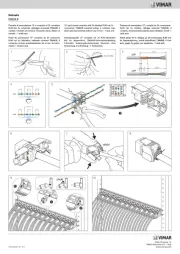
COLLEGAMENTO CON 01876.120 E MODULO/STRISCIA LED RGB
L1 S L2
L
N
Bus
S
S
N
L
+
R
G
B
R G B
20529.120
19529.120
14529.120
01876.120 Modulo LED RGB
Strisce LED RGB
Lunghezzamassimadeicavidicollegamentotral’attuatoreperregolatoreeilregolatoreSLAVEuniversale:100m
MASTER e SLAVE devono essere configurati nella stessa modalità di funzionamento.
NeiregolatoriSLAVEad1moduloutilizzareunfusibilerapidoadaltopoterediinterruzionetipoF5AH250V
ATTENZIONE AI COLLEGAMENTI DELL’ATTUATORE PER REGOLATORE: morsetto L1 al neutro ed
il morsetto L2 alla fase.
Eikon
20529.120
Arké
19529.120
Idea
16969.120
Plana
14529.120
L1 S L2
L
N
Bus
S
S
N
L
+
-
20529.120
19529.120
16969.120
14529.120
01874.120 - 01875.120
Modulo LED RGB
Strisce LED RGB

Viale Vicenza, 14 - 36063 Marostica VI Italy
Tel. +39 0424 488 600 - Fax (Export) +39 0424 488 709
www.vimar.com
L1 S L2
L
N
Bus
S S S
20529.120
19529.120
16969.120
14529.120
20137.120
19137.120
16604.120
14137.120
20137.120
19137.120
16604.120
14137.120
20416
19416
16460
14416
20416
19416
16460
14416
120
120
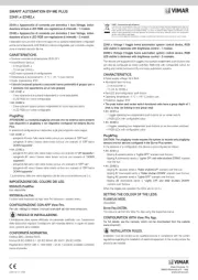
Control device with two rocker switches and actuator for SLAVE dimmers
120 V~ 60 Hz, for LED lamps, electronic transformers, RGB LED lamps, RGB
electronic power supplies, to be completed with interchangeable buttons with
1 or 2 modules - 2 modules.
Thedevicecannotcontroltheloaddirectly.Itisbeusedasadoubleorsinglebutton,depen-
dingonthekeychosen.ThebuttonscanbeconfiguredindependentlyfromtheSLAVEdimmer
controllerandtheycanbepressedatboththetopandbottom.
CHARACTERISTICS.
• RatedsupplyvoltageTPBusbar:29V
• Ratedsupplyvoltagemains:120V~,60Hz
• AbsorptionfromTPBusbar:13mA
• Combinablebuttons: doubleor1single
• Terminals: synchronization,TPbusbarL1 L2 S, ,
• Possiblefunctionsofthebuttons:
- ON/OFF switch
- Roller shutters control
- Dimmer control
- Activation of 2 scenarios
• Functionsthatcanbeaccomplishedwiththedimmer:
- Switching on, off and dimmering
-Changingabsolutecolour
-Hue/saturation/brightnessadjustment
-FADING-SHOWoperation
- “Flash start” mode for CFL lamps
- "Ramp" operation
- Switch-off delay and warning function
-Phasecutting:LE/TE
• Not compatible with By-me control panels with 2 modules and flush-mounted (art.
20510, 16950 and 14510).
•The RGB function is not supported by Article 16969.120.
CONFIGURATION.
FOR THE OPERATIONS OF INSTALLATION AND CONFIGURATION, SEE THE BY-ME
SYSTEM INSTRUCTIONS MANUAL ATTACHED TO THE CONTROL UNIT.
Configuration must be done with the device without the key to be able to press the central
configurationbutton.
• Functionalunits:3(2buttons,1dimmeractuator),eachfunctionalblockcanbelongtoatmost
4 groups.
•Selectionofthefunctionalunitintheconfigurationphase:
-Presstheconfigurationbuttonandwaitfor3stoselectthedimmerfunctionalunit;
-Presstheconfigurationbuttonandthenthedesiredbuttontoselect
therelevantbuttonfunctionalunit.
The configuration starts when the red LED comes on and ends when it goes out.
Whenthedeviceisnotconfigured,theactuatoriscontrolledbytheleft-handbutton.
•Ifthedevicemustbeconfiguredasadoublebuttonyouneedtopresstheleftbutton.
It is recommended to configure the device with the load OFF.
INSTALLATION RULES.
Installationshouldbecarriedoutincompliancewiththecurrentregulationsregardingtheinstal-
lation of electrical systems in the country where the products are installed.
• Itshouldbeusedindry,dust-freeplacesatatemperatureofbetween-5°Cand+45°C.
•Overloading,powersurgesandshort-circuitsmayirreparablydamagedimmers.Beforeinstal-
lationcheckthecircuitcarefullyandeliminateanyoftheabovecauses.
•Thedimmerdoesnothaveamechanicalcircuitbreakerinthemaincircuitandsoisnotgal-
vanicallyseparated.Thecircuitloadshouldbeconsideredalwayspowered.
For further instructions see the manual enclosed with the control panel.
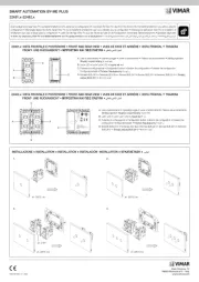
TP Bus terminals
FRONT AND REAR VIEW
Configuration button
LED L1 S L2
CONNECTION WITH UNIVERSAL SLAVE DIMMER
L1 S L2
CONNECTION WITH 01874.120-01875.120
L1 S L2
L
N
Bus
S
S
N
L
+
-
20529.120
19529.120
16969.120
14529.120
01874.120 - 01875.120
MaximumlengthofconnectioncablesbetweenthedimmeractuatorandthedimmerableLEDlampordim-
merableelectronicpowersuppliesforLED:100m
PAY ATTENTION WHEN CONNECTING THE DIMMER ACTUATOR: terminal L2 to neutral and terminal
L1 to phase.
CONNECTION WITH 01876.120
L1 S L2
L
N
Bus
S
S
N
L
+
R
G
B
R G B
20529.120
19529.120
14529.120
01876.120
MaximumlengthofcablesconnectingthedimmeractuatoranduniversalSLAVEdimmer:100m
MASTERandSLAVEmustbeconfiguredinthesameoperatingmode.
PAY ATTENTION WHEN CONNECTING THE DIMMER ACTUATOR: terminal L1 to neutral and terminal
L2 to phase.
Eikon
20529.120
Arké
19529.120
Idea
16969.120
Plana
14529.120
RGB LED module
RGB LED strip
RGB LED module
RGB LED strip
Controllable loads
Max no.
20529.120
19529.120
14529.120
16969.120
SLAVE dimmers
(20137.120-19137.120-16604.120-14137.120-01871.120)
3 3
Lamps
(02662.120 o 02663.120)
10 Not applicable
Adjustableelectronicpowersupplies
(01874.120-01875.120)
10 10
AdjustableRGBelectronicpowersupplies
(01876.120)
10 Not applicable

Viale Vicenza, 14 - 36063 Marostica VI Italy
Tel. +39 0424 488 600 - Fax (Export) +39 0424 488 709
www.vimar.com
L1 S L2
L
N
Bus
S S S
20529.120
19529.120
16969.120
14529.120
20137.120
19137.120
16604.120
14137.120
20137.120
19137.120
16604.120
14137.120
20416
19416
16460
14416
20416
19416
16460
14416
120
120
Appareil de commande à deux boutons va-et-vient et actionneur pour varia-
teurs ESCLAVES 120 V~ 60 Hz, pour lampes LED, transformateurs électro-
niques LED, lampes RGB, alimentations électroniques RGB, à compléter avec
des touches interchangeables 1 ou 2 modules - 2 modules.
Ledispositifnecommandepasdirectementlacharge.Ildoitêtreutilisécommeboutondouble
ou simple, selon la touche choisie. Les boutonspeuvent également être configurés indépen-
dammentdupilotageduvariateurESCLAVE.Onpeutappuyersurleurpartiehauteoubasse.
CARACTÉRISTIQUES.
• Tensionnominaled'alimentationBUSTP:29V
• Tensionnominaled'alimentationréseau:120V~,60Hz
• AbsorptiondubusTP:13mA
• Touchesàassocier:doubleou1simple
•Bornes: synchronisme,busTPL1 L2 S, ,
• Fonctionspouvantêtreréaliséesaveclestouches:
- interrupteur On/Off
- commande pour volets
- commande pour variateur
- activation de 2 scénarios.
•Fonctionspouvantêtreréaliséesaveclevariateur:
- allumage, extinction et réglage
-changementdecouleurabsolue
- réglage tonalité/saturation/luminosité
-fonctionFADING-SHOW
- mode Flash Start pour lampes CFL
- fonction « rampe »
- retard de désactivation et fonction « pré avertissement »
-coupuredephase:LE/TE
•Incompatible avec les centrales By-me 2 modules encastrables (20510, 16950, 14510).
• La fonction RGB n’est pas étayée par l’article 16969.120.
CONFIGURATION.
POUR L'INSTALLATION ET LA CONFIGURATION, VOIR LE MANUEL D'INSTRUCTIONS
DU SYSTÈME By-me JOINT À LA CENTRALE DE COMMANDE.
Exécuter la configuration sans les touches du dispositif pour pouvoir appuyer sur le bouton
central de configuration.
•Blocsfonctionnels:3(2boutons,1actionneurvariateur);chaqueblocfonctionnelpeutappar-
tenir à 4 groupes maximum.
•Sélectiondublocfonctionnelpendantlaconfiguration:
-appuyersurleboutondeconfigurationetattendre3spoursélectionnerleblocfonctionnel
duvariateur;
-appuyersurleboutondeconfigurationpuissurunetoucheauchoixpoursélectionner
leblocfonctionnelcorrespondantaubouton.
Laconfigurationcommencelorsquelaledrouges'allumeetseterminelorsqu'elles'éteint.
Tantqueledispositifn'estpasconfiguré,l'actionneurestcommandéparlatouchegauche.
•Siledispositifdoitêtreconfigurécommeunboutondouble,appuyersurleboutondegauche.
Il est conseillé de configurer le dispositif lorsque la charge est éteinte.
CONSIGNES D'INSTALLATION.
Lecircuitdoitêtreréaliséconformémentauxdispositionsquirégissentl'installationdumatériel
électrique en vigueur dans le pays concerné.
• S'utilisedansunendroitsecetnonpoussiéreux,àunetempératurecompriseentre-5°Cet+45°C.
• Les surcharges,arcs électriques et courts-circuits peuvent endommager irrémédiablement
levariateur.Avantl'installation,vérifiersoigneusementlecircuitet éliminerlesrisques exposés
ci-dessus.
• Levariateur dépourvu decoupuremécanique surle circuitprincipal n'assurepas l'isolation
galvaniquedudispositif.Lecircuitcôtéchargedoitêtreconsidérécommeétanttoujourssous
tension.
•Pourconsulterlesinstructions,voirlemanuellivréaveclacentraledecommande.
bornes bus TP
VUE AVANT ET ARRIÈRE
Bouton de configuration
LED L1 S L2
BRANCHEMENT AVEC VARIATEUR ESCLAVE UNIVERSEL
L1 S L2
BRANCHEMENT AVEC 01874.120-01875.120
L1 S L2
L
N
Bus
S
S
N
L
+
-
20529.120
19529.120
16969.120
14529.120
01874.120 - 01875.120
Longueurmaximaledescâblesdeliaisonentrel'actionneurduvariateuretlalampeLEDàintensitévariable
oulesalimentationsélectroniquesvariablespourLED:100m
ATTENTION AUX BRANCHEMENTS DE L'ACTIONNEUR POUR VARIATEUR: borne L2 au neutre et
borne L1 à la phase.
BRANCHEMENT AVEC 01876.120
L1 S L 2
L
N
Bus
S
S
N
L
+
R
G
B
R G B
20529.120
19529.120
14529.120
01876.120
Longueurmaximaledescâblesdeliaisonentrel'actionneurpourvariateur etlevariateurESCLAVEuniversel:
100 m.
MAÎTRE ET ESCLAVE doivent être configurés selon le même mode de fonctionnement.
ATTENTION AUX BRANCHEMENTS DE L'ACTIONNEUR POUR VARIATEUR: borne L1 au neutre et
borne L2 à la phase.
Eikon
20529.120
Arké
19529.120
Idea
16969.120
Plana
14529.120
Module LED RGB
Bande de LED RGB
Module LED RGB
Bande de LED RGB
Charges commandées
Nbre max
20529.120
19529.120
14529.120
16969.120
Variateurs ESCLAVES
(20137.120-19137.120-16604.120-14137.120-01871.120)
3 3
Lampes
(02662.120 o 02663.120)
10 Non applicable
Alimentationsélectroniquesréglables
(01874.120-01875.120)
10 10
AlimentationsélectroniquesRGBréglables
(01876.120)
10 Non applicable
Product specificaties
| Merk: | Vimar |
| Categorie: | Niet gecategoriseerd |
| Model: | 14529.120 |
Heb je hulp nodig?
Als je hulp nodig hebt met Vimar 14529.120 stel dan hieronder een vraag en andere gebruikers zullen je antwoorden
Handleiding Niet gecategoriseerd Vimar
2 September 2025
26 Augustus 2025
26 Augustus 2025
26 Augustus 2025
14 Augustus 2025
5 Juli 2025
5 Juli 2025
5 Juli 2025

5 Juli 2025
24 Mei 2025
Handleiding Niet gecategoriseerd
- Sogo
- Gys
- Sunding
- Alienware
- Portkeys
- Compex
- XP-PEN
- Pangea Audio
- Asko
- D'Addario
- Bessey
- Holland Electronics
- Spin Master
- Adax
- Fakir
Nieuwste handleidingen voor Niet gecategoriseerd
15 September 2025

15 September 2025

15 September 2025

15 September 2025

15 September 2025
15 September 2025

15 September 2025
15 September 2025
15 September 2025

15 September 2025