Valcom VIP-9831AL Handleiding
Bekijk gratis de handleiding van Valcom VIP-9831AL (3 pagina’s), behorend tot de categorie Speaker. Deze gids werd als nuttig beoordeeld door 41 mensen en kreeg gemiddeld 4.6 sterren uit 7 reviews. Heb je een vraag over Valcom VIP-9831AL of wil je andere gebruikers van dit product iets vragen? Stel een vraag
Pagina 1/3
1 086 947
CAUTION: To reduce the risk of electric shock,
Do not remove cover.
No user serviceable parts inside.
Refer servicing to qualied service personnel.
CAUTION
RISK OF ELECTRIC SHOCK
DO NOT OPEN
This symbol indicates that dangerous
voltage constituting a risk of electric
shock is present within this unit.
This symbol indicates that there are
important operating and maintenance
instructions in the literature accompanying
this unit.
ISSUE 1
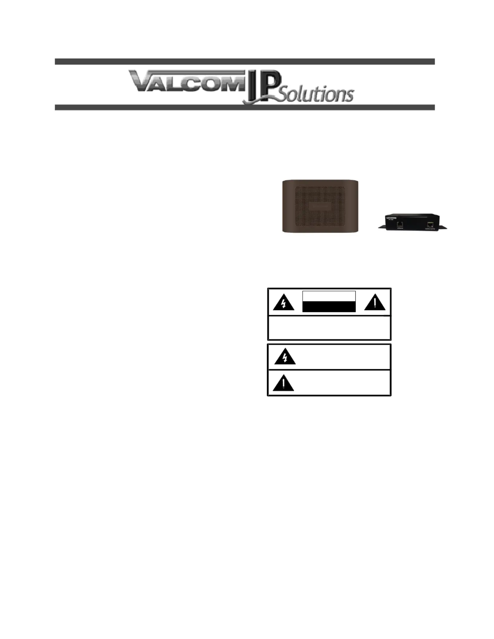
VIP-AL IP /Outdoor Stealth Horn 9831Indoor
INTRODUCTION
The VIP-9831AL IP Stealth Horn is a
self-contained paging system which enables voice
paging hundreds of feet from an Ethernet connection.
The VIP-9831AL consists of a horn and
Network/Aud Interface allowing standalone io
capability when used with a SIP enabled telephone
system or can be accessed from a variety of Valcom
managed VoIP products.
SPECIFICATIONS
Access Methods
SIP telephone system
PBX, FXO Port w/VIP-811A
POTS telephone set w/VIP-A 811
PBX, FXS Port w/VIP-821A
Valcom M Cast Page Group
Features
-network connection RJ45
Network activity LEDs
Power over Ethernet (PoE) 802.3af compatible
Dimensions/Weight
Horn Enclosure:
9.3 "H x 15.0 "W x 5.0 "D
(23.6 cm x 38.1 cm x 12.7 cm)
Wei ght: 5.5 lbs (2.05 kg)
Network Interface
1.62” H x 5.63” W x 3.45” D
(4.11 cm) x (14.30 cm) x (8.76 cm)
W (20.87 cm) with brackets–8.22”
Weight: 2.10 lbs. (0.95 kg)
Environment
Network Interface:
Temperature: +32 to +104°F (0 to +40°C)
Humity: 0 to 85% non-precipitating di
Indoor installation only
Horn Enclosure:
Temperature: -4 to +131°F (-20 to +55°C)
Humidity: 0 to 95% non-condensing
Indoor/Outdoor installation
Power
Via 802.3af PoEthernet Switch: Class 3 E
Precautionary Designations
INSTALLATION
FCC Information
This equipment has been tested and found to
comply with the limits for a Class A digital device,
pursuant to Part 15 of the FCC Rules. These
lits are designed to provide reasonable im
protection against harmful interference when the
equipment is operated in a commercial
environment. This equipment generates uses
and can radiate radio frequency energy and if not
installed and used in accordance wh the it
instruction manual, may cause harmful
interference to radio communications. Operation
of this equipment in a residential area may cause
harmful interference in which case the user will
be required to correct the interference at his own
expense.
Product specificaties
| Merk: | Valcom |
| Categorie: | Speaker |
| Model: | VIP-9831AL |
Heb je hulp nodig?
Als je hulp nodig hebt met Valcom VIP-9831AL stel dan hieronder een vraag en andere gebruikers zullen je antwoorden
Handleiding Speaker Valcom

27 Maart 2026
27 Maart 2026
23 Maart 2026
3 Maart 2026
29 November 2025
26 November 2025
11 November 2025
11 November 2025
10 November 2025
10 November 2025
Handleiding Speaker
Nieuwste handleidingen voor Speaker
2 April 2026
2 April 2026
2 April 2026
2 April 2026
2 April 2026
2 April 2026
2 April 2026
2 April 2026
1 April 2026
1 April 2026