Uni-T UT585 Handleiding
Uni-T
Meetapparatuur
UT585
Bekijk gratis de handleiding van Uni-T UT585 (4 pagina’s), behorend tot de categorie Meetapparatuur. Deze gids werd als nuttig beoordeeld door 32 mensen en kreeg gemiddeld 4.2 sterren uit 16.5 reviews. Heb je een vraag over Uni-T UT585 of wil je andere gebruikers van dit product iets vragen? Stel een vraag
Pagina 1/4

I. Safety Information
In order to operate the Tester properly, please read the manual carefully
before use. This manual includes safety information related to use of the Tester.
To ensure your own safety and safe use of the instrument, strictly follow these
safety instructions during the operation.
Caution:
1. Please read and understand the manual before using the Tester.
2. Keep the manual well for future reference.
3. Use the Tester in a procedure as specified in the manual.
4. Please make sure you have already read and understood the all safety
instructions.
5. Strictly follow the safety instructions mentioned below, or it may cause
personal injury or damage to the Tester.
6. The Tester must be operated by properly trained and qualified technical
staff and done under conditions specified in the manual.
7. UNI-T will not be liable for equipment damage or other loss caused by
improper use or violation against safe operation rules in the manual.
Safety symbol of h as 3 m eanings in the m anual. P lease p ay a ttention
to operation when reading the manual.
Danger: Specifies conditions and actions that most likely pose
severe or fatal harm to the user.
Warning: Specifies conditions and actions that may pose severe
or fatal harm to the user;
Caution: Specifies conditions and actions that may cause minor
injury or damage to the Tester
Danger
Warning
Caution
Meanings of related symbol marks for the instrument:
Danger, Warning, Caution Double or Reinforced Insulated
Conforms to European Union standards
II. Product Features
III. Technical Specifications
3.1 Measurement Range and Accuracy:
(Temperature: (23±5) ℃; Humidity: 45% ~ 75%RH); Altitude: ≤2000m)
Accuracy: ± (2% of reading + b digits)
Function Operating
Voltage(AC)
Rated Trip
Current(I n) △Trip Time Accuracy
Trip Current Trip Time
*1/2
*1
*2
*5
230V (Error
scope: 10%)
Frequency:
50Hz
(10/2 /30 0/100/300/500)mA
(10/2 /30 0/100/300/500)mA
(10/20/30/100/300)mA
(10/20/30/100)mA
(10/20/30/100/
300/500)mA
(0~1000)mS
(0~300)mS
(RAMP increment:
Step size is 10%)
I n varies from 20%
to 110% 300*10mS
(T
esting
period scope
is from 0 to 300mS.)
10
%~0%
0%~+10%
-10%~+10%
(0.6%+4)
Function Range Resolution Accuracy Input protection Note
Ac voltage (60~400)V 1V (5%+2)V
500VAC/7 DC00V
Input impedance
is about 9.9 M
UT583
AUTO
RAMP test
Function Operating
Voltage(AC)
Rated Trip
Current(I n) △ Trip Time Accuracy
Trip Current Trip Time
*1/2
*1
*2
*5
230V (Error
scope: 10%)
Frequency:
50Hz
(10/20/30/100/300/500)mA
(10/2 /30 0/100/300/500)mA
(10/20/30/100/300)mA
(10/20/30/100/200)mA
(10/20/30/100/
300/500)mA
(0~1000)mS
(0~300)mS
Step at 10%;
from 20%~110%
of Rated Current,
300ms *10ms
(Test Time Range:
0~300ms)
Error scope: - %~10 0%
Error scope:
0%~+10%
Error scope:
-10%~+10%
(0.6%+4)
Function Range Resolution Accuracy Input protection Note
1V (5%+2)V
500VAC/7 DC00V
Input
impedance
is about
9.9M
UT585
AUTO
RAMP test
Caution:
1. Frequency response is 50Hz for UT583/585 AC voltage test.
2. Testing value is only for reference if AC/DC voltage is less than 60V.
Ac voltage (60~400)V 1V
Dc voltage
( 6 4 V0~ 00)
3.2 Test Functions
*1/2-------------------------------Non-trip test, check RCD sensitivity
*1--------------------------------- Measure trip time
*2--------------------------------- Measure fast trip time at I n×2 trip current△
*5--------------------------------- Measure fast trip time at I n×5 trip current△
AUTO RAMP test------------ Measure trip current
3.3 Application Standards:
IEC 61010-2 CATIII 300V; Pollution level: 2
IEC 61557-1, 5
IEC 61326-1
IEC 61326-2-2
3.4 Operating Voltage
230VAC 10%)/50Hz
3.5 Operating Environment
Temperature: 0 ~40
Relative humidity: 80%RH
Altitude: 2000m
3.6 Storage Conditions
Temperature: -20 ~60
● This Tester is only applicable for single-phase 230V(±10%)/50Hz
mains supply.
● Do not touch any exposed conductor during test.
● You can touch tested conductor only under a totally safe conditions
during test.
● Remove the test leads immediately from the power supply after test.
●Do not keep test leads connected onto the power for a long time.
● Never open the Tester’s casing during test, for hazardous voltage may
be present inside. If any fault happens, please have the Tester serviced
by professional personnel.
● If the Tester works abnormally(e.g. incomplete display, unexpected value,
damaged casing, noise during test indication), please send it to professional
staff for repair before using the Tester.
● Do not use the Tester if the operator’s hands are wet.
● For the sake of your safety, use only the certified test leads supplied by
our company, prohibit replacing by any other test leads during test.
● Do not expose the Tester to any sunshine, extreme temperature/humid
-ity environments.
● Clean the Tester with soft dampened cloth or mild detergent. Do not use
any abrasives or corrosives.
● Dry the Tester before storing it if it is wet.
( )
● Adopts intelligent micro-controller chip to maintain high accuracy, high
reliability and stability.
● Wiring Check:
LCD Indication Connection Status
L-N&L-PE flash abnormal power supply or no
supply to tested circuits
L-PE&N-PE flash, L-N doesn’t flash the tested terminals are badly or
not earthed.
L-N&N-PE flash, L-PE doesn’t flash neutral terminal is open
L-N,L-PE and N-PE flash wrong wiring to tested terminals,
the Tester will prohibit the tests regarding the above status, except reverse
connection between earth and neutral terminals,
● The tests can be performed at positive 0 orPhase Angle Selection:
negative 180 phase angle.
●Test Locked: The Tester will automatically carry out the tests once the
test leads are connected to the tested terminals (UT585 Only)
●Auto Ramp: Measure trip current and trip time simultaneously.
● 300ms” or “ 1000ms” when trip time Overload Indication: Display “> >
exceeds Max. test time.
● The readings will be frozen when the test finishes.Data Hold:
●1A Large-Current Trip Test(UT585 Only)
●Overheat Check: When internal components inside the Tester is
overheated, LCD will display , and the Tester will automatically
prohibit the tests. After it is cooled down, displays and the tests can
restart.
●Backlight: Press LIGHT button to turn on/off the backlight.
●Low Battery Indication: When battery voltage is 7V, shows, <
please replace the battery timely.
●Auto Power Off: The Tester will automatically power off after ten minutes'
idling. To disable the function, press and hold 0 / 180 button while
turning on the instrument.
●Fused Protection


Relative humidity: 75%RH
3.7 Outline Dimension
210mmx175mmx90mm
3.8 Instrument Weight
About 1,000g
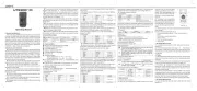
IV
. Tester Description and Main Accessory
(See Figure 1,2&3)
Figure 1
Figure 2 Figure 3
LCD display
PHASE (0 /180 ) key
Current setup (UP/DOWN) key
LIGHT key
TEST key
Function selection switch
Input Terminals
Test Lead
V. RCD Test
Figure 4
Manual content is subject to changes without notice.
** END **
( )
3.9 Accessories:
Test Lead (1.5m) -------------------------1pc
Manual--------------------------------------1pc
Gallus/Tool Case----------------------------1set
Red(Live)
Green(Earth)
Blue(Neutral)
(1)Test Lead Connections
Connect three connectors of the test lead respectively to three input terminals
of the Tester: Red—L, Green—E, Blue—N, then connect another terminal of
the test lead to tested circuit (230V/50Hz power socket).
(2)Voltage Test
Set the rotary switch to V position, The tester now can measure the voltage
between L and N terminals, which should fall within 207V-253V, if not, please
check if the wiring is correct before proceeding into next step. Besides, DC
voltage test is available in Model UT585, when DC voltage test is needed
during other measurements, connect test leads into L and N input terminals
to begin the test.
(3)Wiring Check
Turn the rotary switch to RCD ranges and check the wiring status indicated
on LCD.
LCD Indication Connection Status
L-N&L-PE flash abnormal power supply or no supply
to tested circuits
L-PE&N-PE flash, L-N doesn’t flash the tested terminals are badly or not
earthed.
L-N&N-PE flash, L-PE doesn’t flash neutral terminal is open
L-N, L-PE and N-PE flash wrong wiring to tested terminals,
the Tester will prohibit the tests regarding the above status, please check
the wiring and correct the connection before restart the tests.
(4) Press I n Up or DOWN button to adjust the trip current (I n) the same △ △
as the rated trip current marked on RCD.
Default value: I△n 30mA 0
(5) Test
5.1 Set the rotary switch to test parameters
●Non-Tripping ×1/2: Max. trip time up to 1000ms
●Tripping ×1: Max. trip time up to 1000ms
●Fast Tripping ×2: Max. trip time up to 1000ms
●Fast Tripping ×5: Max. trip time up to 300ms
●AUTO RAMP Test: 20%~110% of rated trip current(I n), Max. trip time up △
to 300ms.
5.2 Press TEST button
●Non-Tripping ×1/2-----The RCD should not trip.
●Tripping ×1: ---------The RCD should trip.
●Fast Tripping ×2:-------- The RCD should trip.
●Fast Tripping ×5:---------- The RCD should trip.
●AUTO Ramp Test: --------The RCD should trip, and trip time and trip current
are displayed simultaneously.
5.3 Press 0 /180 button to set the phase angle and repeat Step 5.1 to
determine the fastest trip time.
5.4 Press to change the phase angle and repeat Step 5.1
5.5 When the tests finish, disconnect the test lead from the tested circuit
immediately.
Danger :Do not touch any exposed earthing metal or conductor during
the operation
(6)Test locked: To enable the test locked function, press and hold TEST
button while turning on the Tester. Then connect the test lead to tested
terminals, the tests can be automatically performed (for UT585 Only)
(7) Backlight: when testing on dimly lighted sites, press LIGHT to turn
on /off the backlight.
(8) Auto Power Off: To disable the function, press and hold 0 / 180
button while turning on the Tester, LCD will show “APO OFF” icon; the Tester
usually defaults at APO ON status(no pressing 0 / 180 button).
VI. Maintenance and Repair
6.1 Replacing the Battery
Please replace the batteries as shown in Figure4(Battery Specifications:
1.5V AA, Alkaline LR6)
Warning:
●To avoid measurement error or cause electric shock or personal injury,
please change the battery timely as soon as low battery indicator
shows.
●Set the rotary switch to OFF position and remove the test leads from input
terminals before replacing the battery.
6.2 Cleaning the Casing: Clean the casing with soft cloth; Do not use any
alcoholic or solvent which may corrode the LCD display; Please keep the
Tester from any moisture.
6.3 Repair
Please contact our after-sale service center or agent if following phenomena
happen:
A. The Tester’s casing or components are damaged;
B. The LCD displays abnormally;
C. Unexpected data shows even under normal use;
D. The buttons don’t function normally or properly;
E. Noise occurs during test.
P/N:110401104559X DATE:2018.06.26 REV.3
Product specificaties
| Merk: | Uni-T |
| Categorie: | Meetapparatuur |
| Model: | UT585 |
Heb je hulp nodig?
Als je hulp nodig hebt met Uni-T UT585 stel dan hieronder een vraag en andere gebruikers zullen je antwoorden
Handleiding Meetapparatuur Uni-T

9 Juni 2025
1 Mei 2025

12 April 2025
5 April 2025

3 April 2025

3 April 2025

3 April 2025

3 April 2025

3 April 2025

3 April 2025
Handleiding Meetapparatuur
- KS Tools
- Ermenrich
- Megger
- Milesight
- Condtrol
- Be Cool
- Ebro
- Crowcon
- Testo
- Aeros
- Black And Decker
- Silverline
- Bresser
- Motrona
- Cablexpert
Nieuwste handleidingen voor Meetapparatuur
29 Juli 2025
29 Juli 2025
29 Juli 2025
29 Juli 2025
29 Juli 2025
29 Juli 2025
28 Juli 2025
28 Juli 2025
28 Juli 2025
28 Juli 2025