Tripp Lite PDU3V20D354A Handleiding
Tripp Lite
Stekkerdoos
PDU3V20D354A
Bekijk gratis de handleiding van Tripp Lite PDU3V20D354A (68 pagina’s), behorend tot de categorie Stekkerdoos. Deze gids werd als nuttig beoordeeld door 60 mensen en kreeg gemiddeld 4.8 sterren uit 30.5 reviews. Heb je een vraag over Tripp Lite PDU3V20D354A of wil je andere gebruikers van dit product iets vragen? Stel een vraag
Pagina 1/68

1. Important Safety 2
Instructions
2. Installation 3
2.1 Mounting the ATS 3
2.2 Mounting the Power Strip 4
2.3 Connecting the Power Strip 4
to the ATS
2.4 Connecting the ATS 5
2.5 Networking the ATS 5
3. Features 6
4. Digital Display 8
5. Using the Digital Display 11
5.1 Navigating Display Menus 11
and Submenus
5.2 Navigating Config Menus 18
and Submenus
6 20. Configuration and Operation
6.1 Automatic Transfer Switch 20
7. Service 22
8. Warranty and Product 22
Registration
Español 24
Français 47
1
Owner’s Manual
PDU330AT6L15, PDU330AT6L21
(Series Number: AG-00D5)
3-Phase 1U Monitored Rack PDU
with Automatic Transfer Switch (ATS)
PDU3VD351
(Series Number: AG-00C2)
PDU3V20D354, PDU3V20D354A, PDU3V20D354B
(Series Number: AG-013C)
3-Phase Vertical Power Strip
1111 W. 35th Street, Chicago, IL 60609 USA • www.tripplite.com/support
Copyright © 2015 Tripp Lite. All rights reserved.
PROTECT YOUR INVESTMENT!
Register your product for quicker service
and ultimate peace of mind.
You could also win an
ISOBAR6ULTRA surge protector—
a $50 value!
www.tripplite.com/warranty
15-05-226-933363.indb 1 6/29/2015 9:07:59 AM

2
SAVE THESE INSTRUCTIONS
This manual contains instructions and warnings that should be
followed during the installation, operation, and storage of this product.
Failure to heed these instructions and warnings may affect the
product warranty.
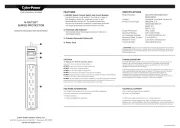
• The Power Strip provides the convenience of multiple outlets, but DOES NOT provide surge or
line noise protection for connected equipment.
• Do not exceed the following equipment ratings:
• Maximum full balanced load is 13.9A per bank when powered by a 3Φ ATS (Automatic
Transfer Switch) with a rated input of 24A.
• Maximum full balanced load is 20A per bank when powered by a 3Φ ATS (Automatic Transfer
Switch) with a rated input of 35A.
• The Automatic Transfer Switch and Power Strip are designed for indoor use only, in a controlled
environment, away from excess moisture, temperature extremes, conductive contaminants, dust
or direct sunlight.
• Keep indoor ambient temperature between 32°F and 104°F (0°C and 40°C).
• The Automatic Transfer Switch and Power Strip must be installed by a qualified technician only.
• Do not attempt to mount the Automatic Transfer Switch or Power Strip to an insecure or
unstable surface.
• Install in accordance with National Electrical Code standards. Be sure to use the proper
overcurrent protection for the installation, in accordance with the plug/equipment rating.
• Connect the Automatic Transfer Switch to an outlet that is in accordance with your local building
codes and that is adequately protected against excess currents, short circuits and earth faults.
• The electrical outlets supplying power to the equipment should be installed near the equipment
and easily accessible.
• Do not connect the Automatic Transfer Switch to an ungrounded outlet or to extension cords or
adapters that eliminate the connection to ground.
• Be sure to provide a local disconnect device on any models that are permanently installed
without a plug that is easily accessible.
• Never attempt to install electrical equipment during a thunderstorm.
• Individual equipment connected to the Power Strip should not draw more current than the
individual outlet’s rating.
• The total load connected to the Power Strip must not exceed the maximum load rating for the
Automatic Transfer Switch.
• Do not attempt to modify the Automatic Transfer Switch’s or Power Strip’s input plugs or power
cables.
• Do not drill into or attempt to open any part of the Automatic Transfer Switch or Power Strip
housing. There are no user-serviceable parts inside.
• Do not attempt to use the Automatic Transfer Switch or Power Strip if any part of it becomes
damaged.
• Use of this equipment in life support applications where failure of this equipment can reasonably
be expected to cause the failure of the life support equipment or to significantly affect its safety
or effectiveness is not recommended. Do not use this equipment in the presence of a
flammable anesthetic mixture with air, oxygen or nitrous oxide.
1. Important Safety Instructions
15-05-226-933363.indb 2 6/29/2015 9:07:59 AM

3
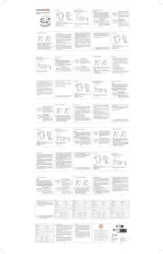
2.1 Mounting the Automatic Transfer Switch (ATS)
Important: The ATS should be installed onto the rack rails in the lowest U space available
(height < 36 in./1 m).
Mount your equipment in a 4-post rack or rack enclosure. The user must determine the fitness of
hardware and procedures before mounting. If hardware and procedures are not suitable for your
application, contact the manufacturer of your rack or rack enclosure. The procedures described in this
manual are for common rack and rack enclosure types and may not be appropriate for all applications.
Note: Each snap-in slide rail assembly consists of a sliding rack enclosure mounting bracket and an inner
channel rail. For ease of installation, the inner channel rails come pre-attached to the ATS unit.
2. Installation
1 Align the rear bracket’s tabs with the rack
enclosure’s square mounting holes and
push the metal hooks through the
mounting holes 1A . Then push the rear
bracket toward the enclosure support for
the blue tabs snap the mount into place
1B . Then align the front bracket’s tabs
with the rack enclosure’s front square
mounting holes. Push the front bracket’s
metal hooks through the mounting holes
and push the front bracket toward the
enclosure support for the blue tabs to
snap the mount into place. Make sure
to install the mounting bracket into
the lowest U space.
2 Repeat step one for the second mounting
bracket on the opposite side of the rack
enclosure.
3 Once both mounting brackets are fixed
onto the rack enclosure, secure the rear
brackets using the included M5X10L
screws.
4 Align the inner channel rails attached to
the ATS with the mounting brackets. Then
slide the unit into the rail assembly. Using
a screwdriver, secure the ATS’s panel-
mounted thumb screws to the rack
enclosure.
1A
1B
3
4
15-05-226-933363.indb 3 6/29/2015 9:08:01 AM
Product specificaties
| Merk: | Tripp Lite |
| Categorie: | Stekkerdoos |
| Model: | PDU3V20D354A |
| Kleur van het product: | Zwart |
| Gewicht: | 4200 g |
| Breedte: | 55.9 mm |
| Diepte: | 56.4 mm |
| Hoogte: | 1778 mm |
| Snoerlengte: | 0.76 m |
| Gewicht verpakking: | 6560 g |
| Breedte verpakking: | 165.1 mm |
| Diepte verpakking: | 1940.6 mm |
| Hoogte verpakking: | 129.5 mm |
| Materiaal behuizing: | Metaal |
| LED-indicatoren: | Ja |
| Aan/uitschakelaar: | Ja |
| Land van herkomst: | China |
| Afmetingen verpakking (BxDxH): | 175 x 150 x 1945 mm |
| Certificering: | Tested to UL60950-1 (USA), CSA (Canada), NOM (Mexico), FCC Class A (Emissions), ROHS |
| Duurzaamheidscertificaten: | RoHS |
| Temperatuur bij opslag: | -15 - 60 °C |
| Bedrijfstemperatuur, bereik: | 32 - 122 °F |
| Hoogte, in bedrijf: | 0 - 3000 m |
| Maximaal vermogen: | 12600 W |
| Afmetingen (B x D x H): | 55.9 x 56.4 x 1778 mm |
| Montage: | Verticaal |
| (Buitenste) hoofdverpakking hoogte: | 180.1 mm |
| (Buitenste) hoofdverpakking breedte: | 374.9 mm |
| (Buitenste) hoofdverpakking brutogewicht: | 11350 g |
| (Buitenste) hoofdverpakking lengte: | 1795 mm |
| Hoeveelheid per (buitenste) hoofdverpakking: | 1 stuk(s) |
| Rackcapaciteit: | 0U |
| AC-ingangsfrequentie: | 50 - 60 Hz |
| Bedrijfstemperatuur (T-T): | 0 - 50 °C |
| Relatieve vochtigheid in bedrijf (V-V): | 5 - 95 procent |
| Aantal AC uitgangen: | 54 AC-uitgang(en) |
| Nominale input voltage: | 200-240 V |
| Stopcontacttypes: | C13 coupler, C19 coupler |
| Stroom (max.): | 35 A |
| PDU types: | Basis |
| Netspanning, in bedrijf: | 200-240 V |
| Aantal masterstopcontacten: | 42 |
| Aantal slavestopcontacten: | 12 |
Heb je hulp nodig?
Als je hulp nodig hebt met Tripp Lite PDU3V20D354A stel dan hieronder een vraag en andere gebruikers zullen je antwoorden
Handleiding Stekkerdoos Tripp Lite

30 Mei 2023

29 Mei 2023

26 Mei 2023

25 Mei 2023

23 Mei 2023

21 Mei 2023

18 Mei 2023

4 Mei 2023

4 Mei 2023

3 Mei 2023
Handleiding Stekkerdoos
- Eaton
- REV
- Icy Box
- Kondator
- Apc
- Anton/Bauer
- Huslog
- Panduit
- Kindermann
- Oehlbach
- Panamax
- Nedis
- Salicru
- Philips
- Legrand
Nieuwste handleidingen voor Stekkerdoos
29 Juli 2025

29 Juli 2025

29 Juli 2025

29 Juli 2025
6 Juli 2025
30 Juni 2025

10 Maart 2025

9 Maart 2025

9 Maart 2025

26 Februari 2025