Traulsen G32010-032 Handleiding
Bekijk gratis de handleiding van Traulsen G32010-032 (20 pagina’s), behorend tot de categorie Koelkast. Deze gids werd als nuttig beoordeeld door 51 mensen en kreeg gemiddeld 4.4 sterren uit 26 reviews. Heb je een vraag over Traulsen G32010-032 of wil je andere gebruikers van dit product iets vragen? Stel een vraag
Pagina 1/20

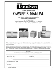
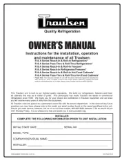
OWNER’S MANUAL
G-Series Reach-In & Pass Thru
Refrigertor, Freezer & Hot Holding
*For equipment produced after 09-15-2017 only.
Hours Of Operation: Monday - Friday 7:30 a.m. - 4:30 p.m.
(CST)
4401 Blue Mound Road Fort Worth, Texas 76106 (USA)
Phone: 800.825.8220 | Service Fax: 817.740.6757 | E-mail: service@traulsen.com | Website: traulsen.com
Quality Refrigeration

TABLE OF CONTENTS
1. THE SERIAL TAG
6. OTHER
A-Service Information Page 6
B-Spare Parts Page 6
C-Warranty Registration Page 6
7. MICROPROCESSOR CONTROL
A-Control Features Page 6
B-Control Panel Page 7
C-Parts Assembly Page 7
D-Notes To The User Page 8
E-Enter The Customer Password Page 8
F-Enter The Technician Password Page 9
G-Service Parameters Page10
H-Adjust The Set Point Page 11
I-Adjust The Set Point Differential Page 11
J-Change The Temperature Scale Page 11
K-Set Date & Time Page 12
L-Set Daylight Savings Page 12
M-Start A Defrost Page 13
N-Set Defrost Mode Page 13
O-Set Defrost Schedule Page 13
P-View The Sensor Temperatures Page 14
Q-Hot Food-Unlocking The Keypad Page 15
R-Hot Food-Adjust The Set Point Page 15
S-Hot Food-Change The Temperature Set Point
(Short Cut) Page 15
T-Hot Food-Turn The Unit Off Page 15
8. SPARE & REPLACEMENT PARTS LISTING Page 16
9. TROUBLESHOOTING GUIDE Page 17
10. WARRANTY INFORMATION Page 18
1. THE SERIAL TAG Page 1
2. RECEIPT INSPECTION Page 2
3. INSTALLATION
A-Location Page 2
B-Packaging Page 2
C-Installing Legs or Casters Page 2
D-Shelf Pins Page 3
E-Removing The Doors & Hardware Page 3
F-Cord & Plug Page 3
G-Power Supply Page 3
H-Wiring Diagram Page 3
I-Clearance Page 4
J-Installing Optional Interior Kits Page 4
K-ON/OFF Switch Page 4
4. OPERATION
A-Refrigerators Page 4
B-Freezers Page 4
C-Light Switches Page 5
D-Turn Off Temperature Display-Main Display
Short Cut Page 5
5. CARE & MAINTENANCE
A-Cleaning The Condenser Page 5
B-Hinge Replacement Page 5
C-Replacing The Gaskets Page 5
D-Cleaning The Exterior Page 6
E-Cleaning The Interior Page 6
F-Adjusting The Shelves Page 6
FORT WORTH, TX. USA
SERIAL MODEL
VOLTS Hz PH
TOTAL CURRENT AMPS
MINIMUM CIRCUIT AMPS
MAXIMUM OVERCURRENT PROTECTION AMPS
LIGHTS WATTS
HEATERS AMPS
REFRIGERANT TYPE OZ
DESIGN PRESSURE HIGH LOW
REFRIGERANT TYPE OZ
DESIGN PRESSURE HIGH LOW
370-60294-00 REV (A)
READING THE SERIAL TAG
• Serial = The permanent ID# of your Traulsen
• Model = The model # of your Traulsen
• Volts = Voltage
• Hz = Cycle
• PH = Phase
• Total Current = Maximum amp draw
• Minimum Circuit = Minimum circuit ampacity
• Lights = Light wattage
• Heaters = Heater amperage (Hot Food units only)
• Refrigerant = Refrigerant type used
• Design Pressure = High & low side operating
pressures and refrigerant charge
• Agency Labels = Designates agency listings
The serial tag is a permanently affixed label upon
which is recorded vital electrical and refrigeration data
about your Traulsen product, as well as the model
and serial number. This tag is located in the upper
right interior compartment on all Traulsen G-Series
refrigerator and freezer models.
G SERIES
Page 1

3. INSTALLATION (cont’d)
3C - INSTALLING CASTERS OR LEGS:
A set of four (4) 6” high casters and sixteen (16) bolts are sup-
plied standard for all Traulsen G-Series units. These are shipped
from the factory packed inside a cardboard box which is strapped
inside the cabinet to the lower shelf.
Legs in lieu of casters are available as an optional accessory
kit for the same models. These are shipped inside a separate
cardboard box. Inside it should contain four (4) legs and sixteen
(16) bolts.
WARNING: THE CABINET MUST BE BLOCKED AND STA-
BLE BEFORE INSTALLING LEGS OR CASTERS.
To install the legs or casters, rst raise and block the reach-in a
minimum of 7” from the oor. For installing legs, thread the legs
into the threaded holes on the bottom of the cabinet (see gure
1). Be certain that all legs are tightly secured. When the unit
is set in its nal position, it is important for proper operation that
the unit be level. The legs are adjustable for this purpose, turn
the bottom of the leg counterclockwise to raise it, clockwise to
lower it. Level the unit from front to back as well as side to side
in this manner.
Please note that Traulsen units are not designed to be moved
while on legs. If the unit requires moving, a pallet jack or forklift
should be used to prevent damage. For installing casters, the
casters are a “plate” type, and require the use of four (4) bolts
each to secure them rmly to the cabinet bottom at each corner
(see gure 2). The caster bolts are tightened using a 1/2”socket
wrench.
Fig. 2
Fig. 1
2. RECEIPT INSPECTION
All Traulsen products are factory tested for perfor-
mance and are free from defects when shipped. The ut-
most care has been taken in crating this product to pro-
tect against damage in transit. All interior ttings have
been carefully secured and the casters/legs are boxed
and strapped inside to prevent damage. Door keys will
be attached to the handle with a nylon strip. The han-
dle is protected by an easily removable nylon netting.
You should carefully inspect your Traulsen unit for
damage during delivery. If damage is detected, you
should save all the crating materials and make note
on the carrier’s Bill Of Lading describing this. A freight
claim should be led within 5 days. If damage is sub-
sequently noted during or immediately after installa-
tion, contact the respective carrier and le a freight
claim. Under no condition may a damaged unit be re-
turned to Traulsen without rst obtaining written permis-
sion (return authorization). You may contact Traulsen
customer care at (800) 333-7447 to request a return.
3. INSTALLATION
3A - LOCATION:
Select a proper location for your Traulsen unit, away
from extreme heat and allow proper clearance for
air circulation (see page 4). Allow enough clear-
ance between the unit and the side wall in order to
make use of the door stay open feature at 120° (self-
closing feature operates up to 90°). The door(s)
must be able to open a minimum of 90° in order to
make use of the maximum clear door width available.
3B - PACKAGING:
All Traulsen units are shipped from the factory bolted to
a sturdy wooden pallet and packaged in a durable Sty-
rofoam backed cardboard wrap.
Most exterior stainless steel and aluminum surfaces
have a protective vinyl covering to prevent scratching
during manufacturing, shipping and installation. After
the unit is installed in place of service, remove and dis-
card the covering from all surfaces.
If at all possible we suggest that the cabinet remain bolted
to the pallet during all transportation to the point of nal
installation. To remove the wooden pallet, the bolts can
then be removed with a 3/4” socket wrench. Avoid laying
the unit on its front, side or back for removal of the pallet.
NOTE: DO NOT LAY THE UNIT ON ITS SIDE DURING
TRANSPORTATION OR INSTALLATION.
G SERIES
Page 2
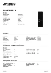
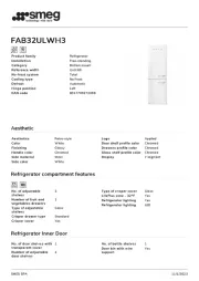
Product specificaties
| Merk: | Traulsen |
| Categorie: | Koelkast |
| Model: | G32010-032 |
Heb je hulp nodig?
Als je hulp nodig hebt met Traulsen G32010-032 stel dan hieronder een vraag en andere gebruikers zullen je antwoorden
Handleiding Koelkast Traulsen

11 Juni 2025

11 Juni 2025

10 Juni 2025
10 Juni 2025

10 Juni 2025

10 Juni 2025

9 Juni 2025

9 Juni 2025

9 Juni 2025
9 Juni 2025
Handleiding Koelkast
- Svan
- Federal
- Kalorik
- OK
- BlueStar
- Luxor
- Cooluli
- AVEA
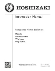
- Hoshizaki
- Adventure Kings
- Pelgrim
- Junker
- Germanica
- Siemens
- Electrolux
Nieuwste handleidingen voor Koelkast
2 Augustus 2025

2 Augustus 2025
2 Augustus 2025
2 Augustus 2025
2 Augustus 2025

30 Juli 2025

30 Juli 2025
30 Juli 2025
29 Juli 2025

29 Juli 2025