Traulsen AHT232NPUT-HHS Handleiding
Bekijk gratis de handleiding van Traulsen AHT232NPUT-HHS (26 pagina’s), behorend tot de categorie Koelkast. Deze gids werd als nuttig beoordeeld door 41 mensen en kreeg gemiddeld 4.3 sterren uit 21 reviews. Heb je een vraag over Traulsen AHT232NPUT-HHS of wil je andere gebruikers van dit product iets vragen? Stel een vraag
Pagina 1/26

This Traulsen unit is built to our highest quality standards. We build our refrigerators, freezers and heat-
ed cabinets this way as a matter of pride. This philosophy has made Traulsen the leader in commercial
refrigeration since 1938. We thank you for your choice and condence in Traulsen equipment and we know
you will receive many years of utility from this equipment.
All Traulsen units are placed on a permanent record le with the service department. In the event of any future
questions you may have, please refer to the model and serial number found on the name tag afxed to the unit.
Should you need service, however, call us on our toll free number, 800-825-8220 between 7:30 am and 4:30 pm
CST, Monday-Friday. It is our pleasure to help and assist you in every possible way.
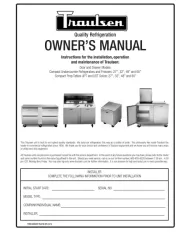
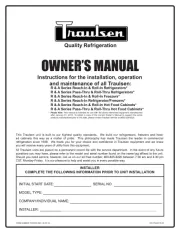
OWNER’S MANUAL
Instructions for the installation, operation
and maintenance of all Traulsen:
R & A Series Reach-In & Roll-In Refrigerators*
R & A Series Pass-Thru & Roll-Thru Refrigerators*
R & A Series Reach-In & Roll-In Freezers*
R & A Series Reach-In Refrigerator/Freezers*
R & A Series Reach-In & Roll-In Hot Food Cabinets*
R & A Series Pass-Thru & Roll-Thru Hot Food Cabinets*
INSTALLER
COMPLETE THE FOLLOWING INFORMATION PRIOR TO UNIT INSTALLATION
INITIAL START DATE: SERIAL NO.
MODEL TYPE:
COMPANY/INDIVIDUAL NAME:
INSTALLER:
FORM NUMBER TR35743 (REV. 09-03-15) P/N 375-60176-00
Quality Refrigeration
* Please Note: This manual is intended for use with the above referenced equipment manufactured
after January 01, 2013. To obtain a copy of the correct Owner’s Manual to support the same
products manufactured prior to this date, please contact Traulsen Service at (800) 825-8220.

TABLE OF CONTENTS
The serial tag is a permanently afxed sticker on which is re-
corded vital electrical and refrigeration data about your Traulsen
product, as well as the model and serial number. This tag is
located in the upper right interior compartment on all reach-in/
pass-thru and roll-in/roll-thru refrigerator, freezer and dual-temp
models. For hot food models, this tag is located on the top of
the unit behind the louvers to protect it from the heat.
I. THE SERIAL TAG
-1-
VII. INTELA-TRAUL®
a-Control Features Page 8
b-Alarm Explanations Page 9
c-Control Panel Page 10
d-Notes To The User Page 10
e-Enter The Customer Access Code Page 10
f-Customer Service Parameters Page 11
g-Adjusting Thermostat Set Point Page 11
h-Adjusting Thermostat Set Point Low Page 12
i-Changing The Temperature Scale Page 12
j-Setting The 24-Hour Clock Page 13
k-Setting The Date Page 14
l-Setting Daylight Savings Time Page 14
m-Starting A Manual Defrost Page 15
n-Setting Defrost Lockouts Page 16
o-Adjusting The Room Temperature Offset Page 17
p-Setting The Audible Alarm Style Page 17
q-Viewing Sensor Temperatures Page 18
r-Door Open Icon Page 18
s-Hot Food Units - Adjusting The Thermostat Page 18
t-Hot Food Units - Turning The Unit OFF & ON Page 19
u-Hot Food Units - Temperature Adjustment Page 19
VIII. TROUBLE SHOOTING GUIDE Page 20
XI. SPARE PARTS LIST Page 21
XII. STAINLESS STEEL OVERVIEW Page 22
XIII. CARE OF STAINLESS STEEL Page 23
XIV. CORROSION REMEDIES Page 23
XV. WARRANTY INFORMATION Page 24
I. THE SERIAL TAG Page 1
II. RECEIPT INSPECTION Page 2
III. INSTALLATION
a-Location Page 2
b-Packaging Page 2
c-Installing Legs or Casters Page 2
d-Shelf Pins Page 3
e-Roll-In Model Installation Page 3
f-Attaching Double Depth Units Together Page 3
g-Installing The Condensate Evaporator Page 3
h-Remote Installation Page 4
i-Cord & Plug Page 4
j-Power Supply Page 4
k-Wiring Diagram Page 4
l-Clearance Page 4
IV. OPERATION
a-Refrigerators Page 5
b-Freezers Page 5
c-Hot Food Cabinets Page 5
V. CARE & MAINTENANCE
a-Cleaning The Condenser Page 5
b-Hinge Replacement Page 6
c-Replacing The Gaskets Page 6
d-Cleaning The Exterior Page 6
e-Cleaning The Interior Page 6
f-Adjusting The Shelves Page 6
g-Replacing The Light Bulb Page 7
VI. OTHER
a-Service Information Page 7
b-Spare Parts Page 7
c-Warranty Registration Page 7

-2-
II. RECEIPT INSPECTION
All Traulsen products are factory tested for performance
and are free from defects when shipped. The utmost
care has been taken in crating this product to protect
against damage in transit. All interior ttings have been
carefully secured and the legs or casters are boxed and
strapped inside to prevent damage. Door keys will be
attached to the handle with a nylon strip. The handle is
protected by an easily removable nylon netting.
You should carefully inspect your Traulsen unit for
damage during delivery. If damage is detected, you
should save all the crating materials and make note on
the carrier’s Bill Of Lading describing this. A freight claim
should be led immediately. If damage is subsequently
noted during or immediately after installation, contact the
respective carrier and le a freight claim within 10 days.
Under no condition may a damaged unit be returned to
Traulsen. without rst obtaining written permission (return
authorization).
III. INSTALLATION
III. a - LOCATION:
Select a proper location for your Traulsen unit, away
from extreme heat or cold. Allow enough clearance be-
tween the unit and the side wall in order to make use of
the door stay open feature at 120° (self-closing feature
operates up to 90°). The door(s) must be able to open
a minimum of 90° in order to make use of the maximum
clear door width available.
III. b - PACKAGING:
All Traulsen units are shipped from the factory bolted
to a sturdy wooden pallet and packaged in a durable
cardboard container. The carton is attached to the
wooden skid with the use of large staples. These should
rst be removed to avoid scratching the unit when
lifting off the crate.
Most exterior stainless steel surfaces have a pro-
tective vinyl covering to prevent scratching during
manufacturing, shipping and installation. After the unit
is installed in place of service, remove and discard the
covering from all surfaces.
To remove the wooden pallet, rst if at all possible, we
suggest that the cabinet remain bolted to the pallet
during all transportation to the point of nal installa-
tion. The bolts can then be removed with a 3/4” socket
wrench. Avoid laying the unit on its front, side or back
for removal of the pallet.
NOTE: DO NOT LAY THE UNIT ON ITS SIDE DURING
TRANSPORTATION OR INSTALLATION.
Roll-Thru models also include special interior wood
bracing, intended to protect the cabinet during shipment.
This bracing should under no circumstances be removed
prior to the unit being installed in its nal location.
WARNING: Read and review these instructions, in their
entirety, BEFORE attempting to disassemble and remove
the interior bracing.
III. INSTALLATION (continued)
III. c - INSTALLING LEGS OR CASTERS:
6” high stainless steel legs are supplied standard for
all Traulsen reach-in and pass-thru units. Casters in
lieu of legs are available as an optional accessory for
the same models. These are shipped from the factory
packed inside a cardboard box which is strapped to
one of the shelves. Remove the nylon strap and open
the box, it should contain either four (4) legs or four (4)
casters and sixteen (16) bolts.
WARNING: THE CABINET MUST BE BLOCKED AND
STABLE BEFORE INSTALLING LEGS OR CASTERS.
To install the legs or casters, first raise and block
the reach-in a minimum of 7 from the floor. For ”
installing legs, thread the legs into the threaded holes
on the bottom of the cabinet (see gure 2). Be certain
that all legs are tightly secured (legs and casters should
be tightened to 300 inch/pounds, max). When the unit
is set in its nal position, it is important for proper op-
eration that the unit be level. The legs are adjustable
for this purpose, turn the bottom of the leg counter-
clockwise to raise it, clockwise to lower it. Level the
unit from front to back as well as side to side in this
manner, using a level placed in the bottom of the
cabinet.
III. b - PACKAGING d): (cont’
If either of the diagonal or upper ceiling braces are
dropped, they could cause personal injury or damage
to the equipment.
To disassemble the bracing, first open the doors
and carefully remove the banding that holds the two
diagonal braces together.
WARNING: The diagonal braces will now be loose and
can fall out of position and possibly permit the ceiling
corner brace to fall.
Carefull remove one diagonal brace while supporting
the ceiling corner brace, so that it does not fall (see
gure 1). Next, remove the ceiling brace, the remaining
diagonal brace, and lastly the oor brace - then discard.
Repeat as necessary for each section of the unit.
Fig. 1
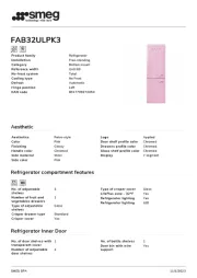
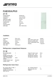
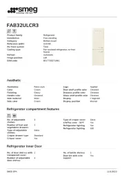
Product specificaties
| Merk: | Traulsen |
| Categorie: | Koelkast |
| Model: | AHT232NPUT-HHS |
Heb je hulp nodig?
Als je hulp nodig hebt met Traulsen AHT232NPUT-HHS stel dan hieronder een vraag en andere gebruikers zullen je antwoorden
Handleiding Koelkast Traulsen

11 Juni 2025

11 Juni 2025

10 Juni 2025
10 Juni 2025

10 Juni 2025

10 Juni 2025

9 Juni 2025

9 Juni 2025

9 Juni 2025
9 Juni 2025
Handleiding Koelkast
- Akai
- Heller
- Airflo
- Frigidaire
- Paulmann
- Moulinex
- Rex
- Ardes
- Flavel
- Philco
- Domo
- Cooluli
- Belling
- Electroline
- ATAG
Nieuwste handleidingen voor Koelkast
2 Augustus 2025
2 Augustus 2025
2 Augustus 2025

2 Augustus 2025
2 Augustus 2025
2 Augustus 2025
2 Augustus 2025

2 Augustus 2025
2 Augustus 2025
2 Augustus 2025