Tekron TCG 01-G Handleiding
Tekron
Niet gecategoriseerd
TCG 01-G
Bekijk gratis de handleiding van Tekron TCG 01-G (52 pagina’s), behorend tot de categorie Niet gecategoriseerd. Deze gids werd als nuttig beoordeeld door 18 mensen en kreeg gemiddeld 4.5 sterren uit 9.5 reviews. Heb je een vraag over Tekron TCG 01-G of wil je andere gebruikers van dit product iets vragen? Stel een vraag
Pagina 1/52

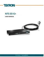
Sixth Edition – Copyright ©2021
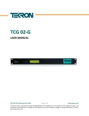
TCG 01-G
USER MANUAL

TEK-TCG 01-G-Manual-v6-052021 P a g e | 2 www.tekron.com
© 2021 by Tekron International Limited. All Rights Reserved. All trademarks are the property of their respective holders. The
information in this document is provided for informational use only and is subject to change. For further information or support,
go to www.tekron.com.
Contents
1. INTRODUCTION ....................................................................................................................... 5
1.1 Product Overview ............................................................................................................................... 5
1.2 Hardware ............................................................................................................................................ 5
1.3 Configuration ...................................................................................................................................... 6
1.4 Accessories .......................................................................................................................................... 6
2. FRONT PANEL........................................................................................................................... 7
LCD Display ................................................................................................................................................ 7
Contrast Adjustment Mode ................................................................................................... 10
LED Indicators ......................................................................................................................................... 11
Alarm Messages ...................................................................................................................................... 12
3. BACK PANEL ........................................................................................................................... 13
P1: Power Input (2-pin Connector [5.08 mm]) ....................................................................................... 13
Earth Stud (M4 Nut) ................................................................................................................................ 13
4. BACK PANEL – INPUTS AND OUTPUTS .................................................................................. 14
ANT: Antenna Connector (SMA Connector) ........................................................................................... 14
Antenna Cable Considerations: ............................................................................................. 14
P2, P3: Programmable Outputs (2-pin [3.81 mm] / BNC or ST Fiber) ..................................................... 16
Electrical and Physical Configuration .................................................................................... 16
If an output is not being used, it may be left unconnected. The dust cap should remain in
place on unused fiber connectors. ........................................................................................ 16
P2, P3 Programmable Output Options .................................................................................. 16
P4: Serial Port and Programmable Output (DB9 Connector).................................................................. 17
P4 Serial Strings ..................................................................................................................... 17
P4 pin 1 Programmable Output ............................................................................................. 18
P5: AM IRIG-B Output (BNC Connector) ................................................................................................. 18
P6: Event Recording / IRIG-B Sync Inputs (4-pin 3.81 mm Connector) .................................................. 19
P7: Sync Relay (4-pin 3.81 mm Connector) ............................................................................................. 19
ADMIN/ETH1: Ethernet Communication Port (RJ-45 Connector) .......................................................... 20
5. SOFTWARE ............................................................................................................................. 21
Configuration Tool .................................................................................................................................. 21
Product specificaties
| Merk: | Tekron |
| Categorie: | Niet gecategoriseerd |
| Model: | TCG 01-G |
Heb je hulp nodig?
Als je hulp nodig hebt met Tekron TCG 01-G stel dan hieronder een vraag en andere gebruikers zullen je antwoorden
Handleiding Niet gecategoriseerd Tekron

6 Mei 2025

6 Mei 2025
6 Mei 2025

6 Mei 2025
6 Mei 2025

6 Mei 2025

6 Mei 2025

6 Mei 2025
Handleiding Niet gecategoriseerd
- CaviLock
- Fisher Price
- Hanseatic
- Mebby
- Duro Pro
- Simmons
- F2
- AJA
- EK Water Blocks
- Schaffner
- HuddleCamHD
- Panamax
- MAAS
- Sigel
- DPM
Nieuwste handleidingen voor Niet gecategoriseerd

11 September 2025
11 September 2025

11 September 2025

11 September 2025

10 September 2025

Epson WorkForce Feed Roller Assembly Kit B12B813561 Handleiding
9 September 2025
9 September 2025
9 September 2025

9 September 2025

9 September 2025