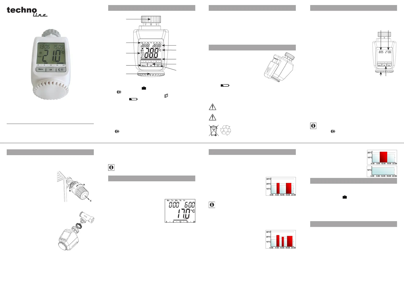
Techno Line TM 3050-RF Handleiding


Lees hieronder de 📖 handleiding in het Nederlandse voor Techno Line TM 3050-RF (4 pagina's) in de categorie Thermostaat. Deze handleiding was nuttig voor 38 personen en werd door 2 gebruikers gemiddeld met 4.5 sterren beoordeeld

Pagina 1/4
A
B
C
D
E
F
G
I
H
J
A
C
B
D
TM 3050-RF
Operation and display General function
This energy-saving controller for radiators can be used to con-
trol room temperature on the basis of time. The actuator moves
a valve, thereby allowing the amount of heat flowing to the heat-
ing appliance to be controlled. The controller is compatible with
all standard heating appliance valves. The large illuminated
display ensures user-friendly operation. A wireless receiver al-
lows the device to receive commands from taught-in system
components.
Installation can be achieved in 3 easy steps.
Step 1: Inserting (replacing) the batteries
Remove the battery compartment cover.•
Insert 2 new LR6 batteries (Mignon/•
AA) int o th e b att ery co mpart ment , en-
suring they are the right way round.
Reattach the battery compartment •
cover and click into place.
New alkaline batteries have a life of
approximately two years. A battery
symbol ( ) will indicate when the batteries need to be re-
placed. After removing the old batteries, please wait approxi-
mately 1 minute before inserting the new ones. This device does
not support operation with rechargeable batteries.
Never recharge standard batteries.
Doing so will present a risk of explosion.
Do not throw the batteries into a fire.
Do not short-circuit batteries.
Used batteries should not be disposed of with
regular domestic waste. Instead, they should
be taken to your local battery disposal point.
Step 3: Installing the energy-saving controller
The actuator can be installed on all standard heating
valves. There is no need to drain away water or fiddle
around with the heating system before doing this. First,
you need to remove the old thermostat dial:
Turn the thermostat dial anti- •
clockwise as far as it will go (A).
Release the thermal ring of the •
thermostat (B).
Remove the thermostat from •
the valve (C).
An adapter will need to be used in
the case of certain valves. Adapters
for Danfoss valves (RA, RAV, RAVL) are included in the scope of
delivery. For details, please refer to
the adapter overview (see 21).
The adapter must be placed on •
the valve and turned until it is se-
curely seated.
In the case of the RAV adapter, •
the extension supplied must be
attached to the valve tappet.
The RA and RAV adapters must, •
in addition, be secured by means
of the bolt and nut supplied.
The energy-saving controller can
only be installed if InS is showing on the display. Follow-
ing installation, the actuator will perform an adjustment run so
that it can adapt to the valve. During this process, AdA will
be displayed.
Place the actuator on the valve.•
Tighten the union nut.•
“InS” will appear on the display, press the OK button.•
The actuator will perform an adjustment run (“AdA” will appear •
on the display, operation not possible).
After that, the actuator will be ready for operation (Auto •
mode).
If the adjustment run was initiated prior to installation, or if
an error message will be displayed (F1, F2, F3); press OK
to move the motor back to the “InS” position.
1. Setting the weekly program
The weekly program allows you to set up to 3 separate
heating periods (7 switching times) for each day of the
week. Programming is performed in relation to the se-
lected days, for which temperatures must be stored for a
period from 00:00 to 23:59.
Press and hold down the menu but-•
ton for more than 3 seconds.
“Pro” will appear on the display.•
Confirm with OK.•
“dAy” will appear on the display. The •
setting wheel can be used to select
an individual day of the week, all
working days, the weekend or the entire week (example
shows working days selected).
Confirm with OK.•
Use the setting wheel to set the first time segment (ex-•
ample shows 0:00 to 6:00).
Confirm with OK.•
Then, select the required temperature for the selected •
time segment (example shows 17.0°C).
Confirm with OK.•
Keep repeating this process until you have finished storing •
temperatures for the period from 0:00 to 23:59.
In Auto mode, the temperature can be modified at any time
via the setting wheel. The modified temperature will then
be retained until the next program changeover.
2. Weekly program: Examples
The energy-saving controller allows you to store up to 3
heating periods (7 switching times) with individual temper-
ature settings for each day of the week. The factory set-
ting consists of two heating phases (from 6:00 until 9:00
and from 17:00 until 23:00 respectively) for every single
day of the week:
From 00:00 to 06:00 17.0°C
From 06:00 to 09:00 21.0°C
From 09:00 to 17:00 17.0°C
From 17:00 to 23:00 21.0°C
From 23:00 to 23:59 17.0°C
To represent the switching periods, the display shows
bars for every other switching interval. In this exam-
ple, no bars are shown for the interval from 0:00 to
6:00. Bars are only shown on the display for the in-
tervals from 6:00 to 9:00 and from 17:00 to 23:00.
If a room also needs to be heated at around noon, the cor-
responding program might look like this:
Monday to Sunday
From 00:00 to 06:00 16.0°C
From 06:00 to 09:00 22.0°C
From 09:00 to 12:00 17.0°C
From 12:00 to 14:00 20.0°C
From 14:00 to 17:30 17.0°C
From 17:30 to 23:30 21.0°C
From 23:30 to 23:59 16.0°C
If you have a home office and only want it to be heated
during the day on working days, you can program the fol-
lowing times:
Monday to Friday
From 00:00 to 08:30 17.0°C
From 08:30 to 17:00 21.0°C
From 17:00 to 23:59 17.0°C
Saturday and Sunday
From 00:00 to 23:59 15.0°C
3. Operating modes
To switch between the 3 operating modes described be-
low, press the menu button briefly (these operating modes
can only be selected following installation/Step 3):
Holiday function• ( ): Set a temperature that is to be
maintained until a fixed point in time.
Manu: • Manual operation The temperature is set manu-
ally using the setting wheel.
Auto: • Weekly program The temperature is control-
led automatically in accordance with the stored weekly
program.
4. Configuration menu
The configuration menu can be used to modify settings. To
access this menu, press and hold down the menu button
(for more than 3 seconds).
Pro: For setting the weekly program (see Section “1 Set-•
ting the weekly program”)
dAt: For modifying the time of day and date•
POS: For querying the actuator’s current position•
dSt: Automatic switchover at the start or end of daylight •
saving time can be deactivated.
AEr: For setting the window opentemperature and •
time so that the temperature is automatically reduced
in the event of ventilation
tOF: For setting the offset temperature•
rES: For restoring the factory settings•
Please read this manual carefully in order to help you put the
device into operation. Keep the manual handy so you can refer
to it at a later date!
A Thermal ring
B Day of the week
C Holiday function ( ), set-back/comfort temperature
( ), manual operation (Manu), automatic operation
(Auto), “window open“ symbol ( ), “battery empty“
symbol ( )
D Menu button: Press and hold down the button for more
than 3 seconds to open the configuration menu
E Setting wheel: For making adjustments (e.g. tempe-
rature)
F Time and date indicator, menu items, functions
G Current temperature setting
H Switching periods set within weekly program
I OK button: For confirming/saving, teaching in
J -button: For switching between set-back and com-
fort temperatures
5
2
6
3
7
4
8
Step 2: Setting the date and time of day
The firmware version number will be displayed briefly once you
have inserted/replaced the batteries and then you will be auto-
matically prompted to set the date and time of day.
Use the setting wheel (C) •
to set the year (B).
Confirm with OK (D).•
Use the setting wheel (C) •
to set the month (B).
Confirm with OK (D).•
Use the setting wheel (C) •
to set the day (B).
Confirm with OK (D).•
Use the setting wheel (C) •
to set the hour (A).
Confirm with OK (D).•
Use the setting wheel (C) •
to set the minute (A).
Confirm with OK (D).•
The motor will start moving back the
control pin while the entries are still being made.
If InS” is displayed with a rotating “∏” symbol, this indi-•
cates that the motor is still moving back. Once the device
is ready for the actuator to be installed on the valve, just
“InS” will appear on the display.
The weekly program and other settings can be cus-•
tomised prior to installation. To do this, press the menu
button when “InS” is shown on the display. For further
details, please see “4. Configuration menu”.
Once programming is complete, “InS” will reappear •
on the display and installation (Step 3) can commence.
When “InS” is visible on the display, you can activa-
te the teach-in function prior to installation by pres-
sing the button briefly.
UnL: For teaching out all taught-in wireless components •
Use the setting wheel to select menu items and the OK but-
ton to confirm your choice. Press the menu button again to
return to the previous level. After 65 seconds without any-
thing happening, the menu will close automatically.
5. Display content during normal operation
During normal operation, the following
are displayed: day of the week, time of
day, date, operating mode, tempera-
ture setting and switching periods.
The bars indicating the weekly pro-
gram’s switching periods are shown
for every other time interval. For an ex-
ample, please refer to “2. Weekly program: Examples”.
6. Teaching in wireless components
The actuator supports the teaching in of up to 4 system
components (e.g. remote control and window contact),
plus 1 wall thermostat.
Press and hold down the OK button for more than 3 seconds.•
The remaining teach-in time will be displayed (30 seconds).•
The device being taught-in now needs to send a wireless •
signal (e.g. press button on remote control).
The display will then switch to the normal view.•
Once this has been done, the actuator will respond to wire-
less commands from taught-in devices. Whenever the ac-
tuator receives a signal from a window contact or remote
control, the display will light up briefly.
7. Teaching out wireless components
Components that have been taught in on the actuator can be
taught out again using the UnL(Unlearn) function. All wire-
less components are taught out at once with this function.
Press and hold down the menu button for more than 3 seconds.•
Use the setting wheel to select the “UnL” menu item.•
Confirm with OK.•
ACC” will appear on the display; press OK to confirm.•
8. Operation with a wall thermostat
If the actuator is going to be operated in conjunction with a wall
thermostat, this thermostat will need to be taught in (see 6). Once
it has been taught in, “ECF will appear on the display. No further
settings can then be made on the actuator and it will no longer
respond to taught-in remote controls or window contacts.
If no wireless signal is received from the wall thermostat
for a period of 60 minutes, the actuator will exit ECF mode.
It will then assume control of the temperature, which it will
continue to regulate in accordance with the weekly pro-
gram until the next wireless signal is received.
To teach outa wall thermostat, you must reinsert the bat-
teries in the actuator (and wait for approx. 1 minute). Once
you have entered the date and time of day, you can use the
menu button (before the adjustment run is initiated) to per-
form the “teach-out” process as described in section 7.
9. Setting the holiday function
If you want a fixed temperature to be maintained for a set
period of time while you are on holiday or during a party,
you can make use of the Holiday function.
Press and release the menu button repeatedly until the •
suitcase symbol ( ) appears on the display.
Use the setting wheel to set the end of the time period •
during which the temperature is to be maintained.
Press the OK button to confirm.•
Then use the setting wheel to set the date.•
Press the OK button to confirm.•
Use the setting wheel to set the temperature; press OK to
confirm. The display will flash to confirm your settings.
The set temperature will remain in force until the speci-
fied time. After that, the actuator will adopt Auto mode.
Wireless commands from the window contact and remote
control will continue to be executed.
10. Comfort and set-back temperatures
The comfort/set-back temperature button ( ) provides an easy
and convenient way of switching between these two tempera-
tures. The factory settings are 21.0°C and 17.0°C respectively.
To adapt them, proceed as follows:
Press and hold down the comfort/set-back temperature but-•
ton ( ) for more than 3 seconds.
The sun symbol ( • ) will appear on the display along
with the current comfort temperature.
Use the setting wheel to modify the temperature; press •
OK to confirm.
The moon symbol ( • ) will appear together with the set-
back temperature.
Use the setting wheel to modify the temperature; press •
OK to confirm.
The temperature can even be modified in Auto mode at any
time by using this button. The new setting will be retained
until the program’s next switching time.
11. Child-proof lock/Operating inhibit
Operation can be inhibited.
To activate/deactivate the operating inhibit, briefly press •
the and Menu buttons at the same time.
Once the function is active, “LOC” will appear on the •
display.
To deactivate the function, press both buttons again.•
12. Setting the heating break
If the heating is being switched off for the summer, you
can save battery power. This involves opening the valve
up fully. Limescale protection measures remain in place.
Wireless commands from the window contact or remote
control will no longer be executed.
To activate the heating break, turn the setting wheel •
clockwise during manual operation ( ) until “On” Manu
appears on the display.
To terminate the heating break, quit manual operation •
( ) or turn the setting wheel anticlockwise.Manu
13. Setting frost protection mode
If you do not want the room to be heated, the valve can
be closed. It will only be opened again if there is a risk of
freezing due to frost. Limescale protection measures re-
main in place. Wireless commands from the window con-
tact or remote control will no longer be executed.
To activate frost protection mode, turn the setting wheel •
anticlockwise during manual operation (Manu) until “OFF”
appears on the display.
To terminate frost protection mode, quit manual opera-•
tion ( ) or turn the setting wheel clockwise.Manu
14. “Window open” function
If the room is being ventilated, the actuator controls the tem-
perature to save on heating costs. While this function is active,
the “window open” symbol ( ) appears on the display.
Without window contact: The actuator will automatically de-
tect a significant drop in temperature due to ventilation. You
can set your own “window open” temperature and time.
With taught-in window contact: The temperature will only
be reduced during the time that the window is left open. You
can set your own “window open” temperature.
Press and hold down the menu button for more than •
3 seconds.
Use the setting wheel to select the “AEr” menu item.•
Confirm with OK.•
Use the setting wheel to set the temperature/time. Then •
press OK to conrm.
Without a taught-in window contact, this function can •
be deactivated by selecting a time of “0.
15. Setting the offset temperature
The temperature is measured at the heating appliance it-
self, with the result that other parts of the room may be
warmer or colder than this. To allow for this, you can set
a temperature offset of ±3.5°C. If, for example, a temper-
ature of 18°C is measured somewhere within the room
instead of the 20°C set, it means that an offset of -2.0°C
needs to be configured.
Press and hold down the menu button for more than •
3 seconds.
Use the setting wheel to select the “tOF” menu item.•
Confirm with OK.•
Use the setting wheel to modify the temperature.•
Press the OK button to confirm.•
16. Restoring the factory settings
You can reset the actuator to its initial state manually. This
will clear all the settings that have been made manually.
Press and hold down the menu button for more than •
3 seconds.
Use the setting wheel to select the “rES” menu item.•
Confirm with OK.•
ACC” will appear on the display; press OK to confirm.•
17. Intended use
The energy-saving controller has been designed for the
purpose of controlling a standard heating appliance valve.
The device may only be operated indoors and must be
protected from the effects of damp and dust, as well as
solar radiation and sources of radiant heat.
Using the device for a purpose or in a manner other than
that described in this operating manual constitutes a
breach of the “intended use” and shall invalidate the war-
ranty and any liability claims. The same shall apply in the
event of any conversion or modification work. The devices
are intended exclusively for domestic use.
18. Troubleshooting and maintenance
Error code on
display Problem Remedy
Battery symbol
( )
Battery power
too low Replace batteries
F1 Valve actuator
sluggish
Check installation, in-
spect heating valve
F2 Adjusting range
too large
Check
actuator
fastening
F3 Adjusting range
too small Check heating valve
F4 1 wall thermostat
already taught in
Teach out devices
F5
4 wireless com-
ponents already
taught in
At 12:00 every Saturday, the actuator performs a weekly
descaling function to prevent valve calcification. “CALwill
appear on the display.
19. Instructions for disposal
Do not dispose of the device with regular
domestic waste.
Electronic equipment must be disposed of at local col-
lection points for waste electronic equipment in com-
pliance with local directives governing waste electrical
and electronic equipment.
The CE sign is a free trade sign addressed exclusively to
the authorities and does not warrant any properties.
22. Information about radio operation
Radio transmission is performed on a non-exclusive trans-
mission path, which means that there is a possibility of in-
terference occurring.
Switching operations, electric motors or faulty electric devices
are some of the reasons why interference may occur. The range
of transmission within buildings can deviate greatly from open
air distances. Besides the transmitting power and the reception
characteristics of the receiver, environmental influences such as
humidity and local structures also play an important role.
TechnoTrade Import-Export GmbH hereby declares that
this device conforms with the essential requirements and
other relevant regulations of Directive 1999/5/EC.
The full declaration of conformity is provided at
www.technoline-berlin.de/Konformitaetserklaerung.
23. Technical properties
Supply voltage: 3 V
Max. current consumption: 100 mA
Batteries: 2x LR6 batteries (Mignon/AA)
Battery life: Approx. 2 years
Display: LC display
Receiver frequency: 868.3 MHz
Housing dimensions: 63 x 76 x 102 mm (W x H x D)
Ambient temperature: +5 to +55°C
Max. surface temperature: +90°C (of radiator)
Linear travel: 4.2 mm
Spring force: max. 80 N
Connection: M30 x 1.5
We reserve the right to make any technical changes that
constitute an improvement to the device.
Issue 1 English 10/2009
Documentation © 2009 TechnoTrade Import-Export GmbH, Wildau.
All rights reserved.
CC-RT-RX-CyE-W-R3, V1.1 907-76
9
13
10
14
11
15
12
16
20. Safety instructions
The devices concerned are not intended for children and must not
be used as toys. Do not leave packaging material lying around,
as children might be tempted to play with it, which is extremely
dangerous. Do not open the device: it does not contain any com-
ponents that need to be serviced by the user. In the event of an
error, please return the device to our service department.
21. Adapter overview
Manufacturer Figure Adapter
Heimeier, MNG, Jun-
kers, Landis&Gyr
“Duodyr, Honeywell-
Braukmann, Oventrop,
Schlösser, Simplex,
Valf Sanayii, Mertik
Maxitrol, Watts,
Wingenroth (Wiroflex),
R.B.M., Tiemme, Jaga
No adapter
required
Danfoss RA
Included
in scope of
supply
Danfoss RAV
Included
in scope of
supply
Danfoss RAVL
Included
in scope of
supply


Product specificaties

Merk: Techno Line
Categorie: Thermostaat
Model: TM 3050-RF

Heb je hulp nodig?

Als je hulp nodig hebt met Techno Line TM 3050-RF stel dan hieronder een vraag en andere gebruikers zullen je antwoorden


Handleiding Thermostaat Techno Line

Handleiding Thermostaat

Nieuwste handleidingen voor Thermostaat