Supermicro X13SAN-E Handleiding
Supermicro Niet gecategoriseerd X13SAN-E
Bekijk gratis de handleiding van Supermicro X13SAN-E (1 pagina’s), behorend tot de categorie Niet gecategoriseerd. Deze gids werd als nuttig beoordeeld door 29 mensen en kreeg gemiddeld 4.5 sterren uit 4 reviews. Heb je een vraag over Supermicro X13SAN-E of wil je andere gebruikers van dit product iets vragen? Stel een vraag
Pagina 1/1
S
UPERMICR
R
ContaCtnformatIonI
•Manuals: http://www.supermicro.com/support/manuals
•Drivers & Utilities: https://www.supermicro.com/wdl/driver/
•Safety: http://www.supermicro.com/about/policies/safety_information.cfm
© 2022 Supermicro Computer Inc. All rights reserved. Reproduction of this document whether in part or in whole is strictly prohibited without Supermicro's written
consent. All Trademarks are property of their respective entities. All information provided is deemed accurate at the time of printing; however, it is not guaranteed.
P CaCkageontents
X13san-H/-e/-L/-C
X13san-H/-e/-L/-C-WoHs
Q r g 1.00uICkeferenCeuIde
•One Supermicro Motherboard
with passive heatsink
(-WOHS without heatsink)
•One Quick Reference Guide
•One Audio Cable (line-out, mic-in)
•One COM Cable
•One SATA Cable
•One SATA Power Cable
•One USB 2.0 Cable
•One DC IN Power Cable
•Website: www.supermicro.com
•General Information: marketing@supermicro.com
•Technical Support: support@supermicro.com
•Phone: +1 (408) 503-8000, Fax: +1 (408) 503-8008
F oryoursystemtoworkproperlypleasedownloadappropriate,
driversimagesusersmanualFromthelinksbelow//' :
MNL-2517-QRG-100
WARNING: This product can expose you to chemicals including
lead, known to the State of California to cause cancer and birth
defects or other reproductive harm. For more information, go
to www.P65Warnings.ca.gov.
!
CPU
JPW1
FAN1
JHDMI1
USB6
USB7
USB4
USB5
JHDMI2
LED1
LAN2LAN1
JGP1
BT1
JF1
JSIM1_OPT
USB0/1
USB2/3
JSPKR1
AUDIO FP
I-SATA0
P1_PE2 4-0
JPH1
COM3/COM4COM1/COM2
JPT1
MH3
MH1
MH4
MH2
SRW1
SRW2
SRW4
SRW5
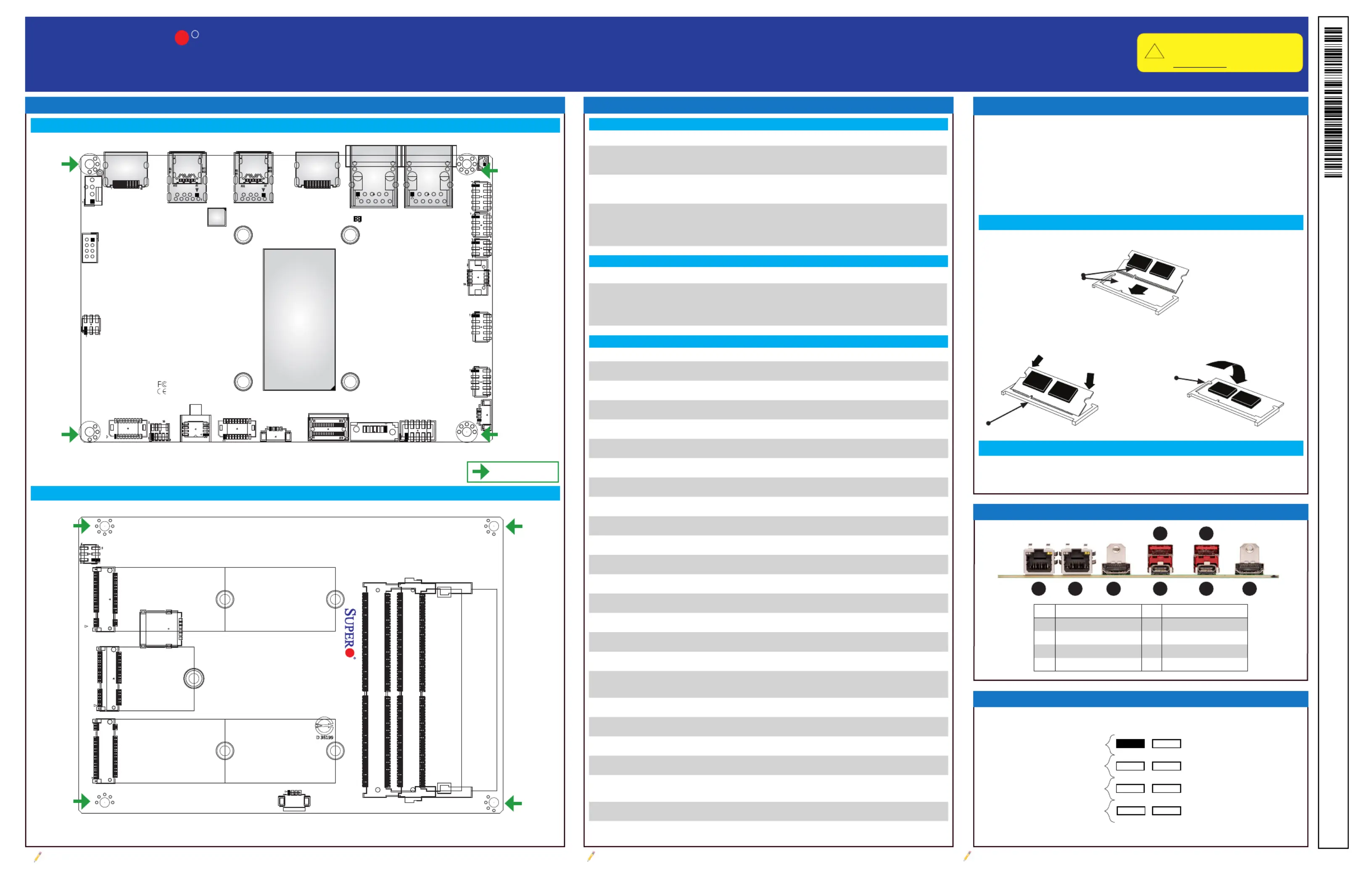
Jumpers, LED Indicators and ConnectorsMotherboard Layout and Features
Note: Graphics shown in this quick reference guide are for illustration only. Your components may or may not look exactly the same as drawings shown in this
guide.
Note: Refer to Chapter 1 of the User Manual for detailed information on jumpers, connectors,
and LED indicators.
Note: Refer to Chapter 2 of the User Manual for detailed information on memory support and CPU/
motherboard installation instructions.
ConnectorDescription
BT1Battery Cable Header
FAN14-pin fan header
AUDIO FPFront panel audio header (line-out, mic-in)
COM1/COM2COM header for two RS232/422/485
COM3/COM4COM header for two RS232
I-SATA0SATA 6Gb/s port
JF1Front Control Panel header
JGP18-bit General Purpose I/O header
JHDMI1Back Panel HDMI 2.0b port
JHDMI2Back Panel HDMI 1.4b port
JPH14-pin HDD power connector
JPW18-pin 12-24V main power-in connector
JSIM1Nano SIM Card slot
JSMBUS1System Management Bus header
JSPKR1Speaker-out with 3W Amplier
LAN1, LAN22.5G RJ45 LAN ports
M.2-B1
M.2 B-Key 2242/2280/3042 slot with a Nano SIM slot and support for SATA
6Gb/s or PCIe 3.0 x1/USB 3.0/USB 2.0
M.2-E1M.2 E-Key 2230 slot for PCIe 3.0 x1/USB 2.0/Intel CNVi
M.2-M1M.2 M-Key PCIe 4.0 p1-x4 2242/2280 slot
P1_PE2 4-0PCIe 4.0 p1-x4 SlimSAS Slot
USB0/1, USB 2/3Front-accessible USB 2.0 headers for four USB 2.0 ports
USB4, USB6
USB 3.2 (10Gb/s)/DisplayPort 1.4 Alt Mode Type-C ports on the rear I/O
panel
USB5, USB7USB 3.2 (10Gb/s) Type-A ports on the rear I/O panel
JumperDescriptionDefault
JPME2
CMOS Clear
Manufacturing Mode
Pins 1-3 (Normal)
Pins 4-6 (Normal)
JPT1
Force Power On
TPM 2.0 Enable/Disable
Pins 2-4 (Force power on)
Pins 1-3 (Enable)
JSIM1_OPT
SIM Detect Option
5G/LTE USB/PCIe Option
M.2 B-Key Storage LED
Pins 2-4 (Low Active)
Pins 1-3 (USB)
Pins 5-6 (Enabled)
LEDDescriptionStatus
LED1Onboard Power LED
Green: System on
Red: S5 or main power fail
Off: System off
LED Indicators
Jumpers
Connectors
6
5
2
1
DESIGNED IN USA
X13SAN-C
REV:1.00
2230
22802280
22422242
JPME2
JSIM1
SRW3
JSMBUS1
M.2-B1M.2-E1M.2-M1
DIMMB1
DIMMA1
SO-DIMM Memory Installation
CPU and Memory Support
Front Control Panel (JF1)
1
4
1
5
1
3
1
7
1
8
1
2
1
6
X13SAN-H/-H-WOHS supports 12th Generation Intel® Core™ i7-1265UE.
X13SAN-E/-E-WOHS supports 12th Generation Intel® Core™ i5-1245UE.
X13SAN-L/-L-WOHS supports 12th Generation Intel® Core™ i3-1215UE.
X13SAN-C/-C-WOHS supports 12th Generation Intel® Celeron® 7305E.
The X13SAN-H/-E/-L/-C and X13SAN-H/-E/-L/-C-WOHS motherboards
support up to 64GB of Non-ECC DDR5 SO-DIMM with speeds of up to 4800
MT/s in two memory slots.
87
3.3V Stby
3.3V
HDD LED
Power LED
21
Reset Button
Power Button
Ground
Ground
##DenitionDescription
152.5G RJ45 LANUSB 3.2 Type-A
262.5G RJ45 LANUSB 3.2/DP 1.4 Type-C
37HDMI 1.4bUSB 3.2 Type-A
4USB 3.2/DP 1.4 Type-CHDMI 2.0b8
Align
1. Position the SO-DIMM module's bottom key so it aligns with the receptive
point on the slot.
2. Insert the SO-DIMM module vertically at about a 45-degree angle. Press
down until the module locks into place. The side clips will automatically
secure the SO-DIMM module, locking it into place.
Insert this end rst
Locking Clip
1. Push the side clips at the end of slot to release the SO-DIMM module.
Pull the SO-DIMM module up to remove it from the slot.
Rear I/O Panel Connectors
1
1
SO-DIMM Memory Uninstallation
Top Layout and Mechanical Drawing
Bottom Layout and Mechanical Drawing
= mounting hole
Product specificaties
| Merk: | Supermicro |
| Categorie: | Niet gecategoriseerd |
| Model: | X13SAN-E |
Heb je hulp nodig?
Als je hulp nodig hebt met Supermicro X13SAN-E stel dan hieronder een vraag en andere gebruikers zullen je antwoorden
Handleiding Niet gecategoriseerd Supermicro

6 April 2026
13 Maart 2026
13 Maart 2026
9 Februari 2026
21 Januari 2026
20 Januari 2026
19 Januari 2026
19 Januari 2026
13 Januari 2026
12 Januari 2026
Handleiding Niet gecategoriseerd
Nieuwste handleidingen voor Niet gecategoriseerd
23 Juli 2026
23 Juli 2026
23 Juli 2026
23 Juli 2026
23 Juli 2026
23 Juli 2026
23 Juli 2026
23 Juli 2026
23 Juli 2026
22 Juli 2026