Supermicro X10SDV-TP8F Handleiding
Supermicro Niet gecategoriseerd X10SDV-TP8F
Bekijk gratis de handleiding van Supermicro X10SDV-TP8F (1 pagina’s), behorend tot de categorie Niet gecategoriseerd. Deze gids werd als nuttig beoordeeld door 24 mensen en kreeg gemiddeld 4.0 sterren uit 9 reviews. Heb je een vraag over Supermicro X10SDV-TP8F of wil je andere gebruikers van dit product iets vragen? Stel een vraag
Pagina 1/1
S
UPERMICR
R
ContaCtnformatIonI
•Manuals: http://www.supermicro.com/support/manuals
•Drivers & Utilities: ftp://ftp.supermicro.com/CDR_Images/CDR-X10-UP/
•Safety: http://www.supermicro.com/about/policies/safety_information.cfm
© 2016 Supermicro Computer Inc. All rights reserved. Reproduction of this document whether in part or in whole is strictly prohibited without Supermicro's written
consent. All Trademarks are property of their respective entities. All information provided is deemed accurate at the time of printing; however, it is not guaranteed.
P CaCkageontents
X10sDV f atX sleXerIes
Q r g r. 1.0uICkeferenCeuIDeeV0
•One (1) Supermicro Motherboard
•Four (4) SATA Cables
•Four (4) Mini-SAS HD Cables (7TP8F/7TP4F)
•One (1) I/O Shield
•One (1) Quick Reference Guide
•Website: www.supermicro.com
•General Information: marketing@supermicro.com
•Technical Support: support@supermicro.com
•Phone: +1 (408) 503-8000, Fax: +1 (408) 503-8008
f oryoursystemtoworkProPerlyPleaseDownloaDaPProPrIate,
DrIVersImagesusersmanualfromthelInksbelow//' :
MNL-1858-QRG-100
WARNING: This product can expose you to chemicals including
lead, known to the State of California to cause cancer and birth
defects or other reproductive harm. For more information, go
to www.P65Warnings.ca.gov.
!
Item #JumperDescriptionDefault
21JBR1BIOS RecoveryPins 1-2 (Normal)
74JBT1CMOS ClearOpen: Normal, Short: Clear CMOS
16, 17JI
2
C1, JI
2
C2SMB to PCI-E SlotsPins 2-3 (Disabled)
14JPB1BMC Enable (Debug use only)Pins 1-2 (Enabled)
18JPG1VGA EnablePins 1-2 (Enabled)
6, 7, 9LAN1, LAN2, LAN3/4/5/6 EnablePins 1-2 (Enabled)JPL1, JPL2, JPL3 (JPL3: TP8F/TP8F)
40JPME1ME RecoveryPins 1-2 (Normal)
64JPME2Manufacturing ModePins 1-2 (Normal)
53JPTG110Gb Ethernet EnablePins 1-2 (Enabled)
20 JPS1 (7TP8F/7TP4F only)SAS 2.0 Enable/DisablePins 1-2 (Enabled)
51JPUSB1USB Wakeup (For USB0/1)Pins 1-2 (Enabled)
22JWD1Watch Dog EnablePins 1-2 (Reset)
BAR CODE
JTGLED1
X10SDV-TP8F
REV:1.01
DIMMB1
DIMMA2
DIMMB2
DIMMA1
BT1
LED3
C
LEDM1
A
C
LED8
C
LED7
A
C
JITP1
DESIGNED IN USA
COM1
1
PRESS FIT
JPS1JPG1JWD1
JPME2
JBR1
JPUSB1
JPL1
JPL2
JPME1
JPL3
JPTG1
JI2C2JI2C1JSMB1JPB1
JNVI2C1
JIPMB1
LEDT4
A
C
LEDT2
A
C
LEDT3
A
C
LEDT1
A
C
LEDS1
A
MP_SRW1
MP_SRW2
JMP1
FAN4
FANA
FANB
FAN1
FAN3
FAN2
JSTBY1
JLANLED1
I-SGPIO1
I-SATA3
I-SATA2
I-SATA0
I-SATA1
JSD1
JSD2
JOH1
JL1
JTPM1
JF1
JSAS4
PRESS FIT
JSAS3
PRESS FIT
JSAS2
PRESS FIT
JSAS1
PRESS FIT
JPW1
JPI2C1
JD1
JGP1
JPH1
JPV1
M2_SRW2
M2_SRW3
M2_SRW1
VGA
LAN 7/8
LAN 5/6
LAN 3/4
LAN 1/2
JOH1-OH
SATA POWER
L-SAS12-15
L-SAS0-3
L-SAS4-7
L-SAS8-11
IPMI_LAN
2-3:DISABLE
1-2:ENABLEJPUSB1:USB0/1 WAKE UP
2-3:DISABLE
LAN3/4/5/6
1-2:ENABLE
JPL3:
ON
PWR
RST
NIC1
L
H
PCI-E 2.0 X1 /
I-SATA5
CPU SLOT7 PCI-E 3.0 X8
CPU SLOT6 PCI-E 3.0 X8
USB 5/6
USB 3/4
USB 2
USB 0/1(3.0)
PCI-E 3.0 X4 / I-SATA4
JMD1: M.2
Intel Xeon
D-1500
SoC
1-2:ENABLE
2-3:DISABLE
JPG1:
2-3:DISABLE
JPL1/JPL2:
1-2:ENABLE
JL1:
2-3:NMI
1-2:RST
JWD1:WATCH DOG
JBT1:
LAN2
LAN1/
CHASSIS
CMOS
INTRUSION
CLEAR
4-7:SPEAKER
1-3:PWR LED
JD1:
1-2:ENABLE
2-3:DISABLE
JI2C1/JI2C2:
UID
1-2:ENABLE
2-3:DISABLE
JPS1:SAS
2-3:DISABLE
1-2:ENABLE
JPTG1:10Gb LAN
JBR1
1-2:NORMAL
2-3:BIOS RECOVERY
LSI
2116
(-7TP4F/-7TP8F)
BMC
AST2400
PHY
10GbE
CS2447
i350
AM4
(-7TP8F/
-TP8F)
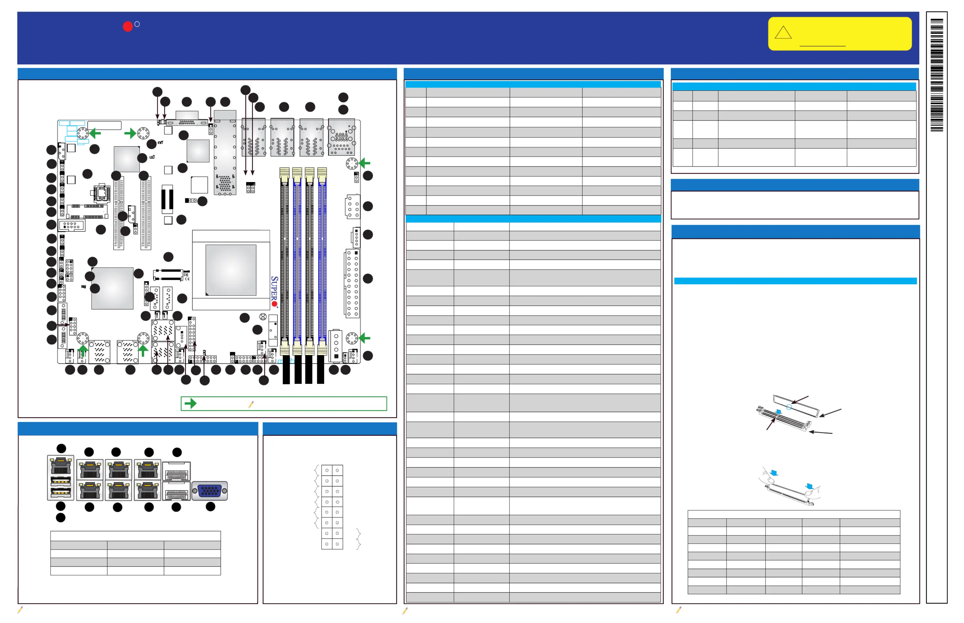
DIMM Memory Installation
Jumpers and Connectors
Memory Support
Motherboard Layout and Features
Jumpers
Note: Graphics shown in this quick reference guide are for illustration only. Your components may or may not look exactly the same as drawings shown in this
guide.
Note: Refer to Chapter 1 of the User Manual for detailed information on jumpers, connectors, and LED indica-
tors.
Note: Refer to Chapter 2 of the User Manual for detailed information on memory support and CPU/
motherboard installation instructions.
= mounting hole
Front Panel Control (JF1)
5
9
14
10
15
4
8
13
3
7
12
17
18
19
20
2
6
11
16
21
26
31
36
41
37
42
43
44
45
46
47
48
49
50
55
54
53
52
51
56
57
58
59
60
65
64
63
62
61
38
39
40
32
33
34
35
27
28
29
30
22
23
24
25
1
Note: Item numbers are shown in counterclockwise order
LED Indicators
Item #LEDDescriptionColor/StateStatus
38LED3Power LEDGreen: OnSystem Power On
12LED7UID Switch LEDBlue: OnUnit Identied
56LED8Overheat/PWR Fail/Fan Fail LEDRed: Solid on
Blinking
Solid On: Overheat,
Blinking: PWR Fail or Fan Fail
57LEDM1BMC Heartbeat LEDGreen: BlinkingBMC: Normal
67LEDS1SAS Heartbeat LED
(7TP8F/7TP4F)
Green: Blinking
Red
SAS Active
SAS Error
LED Indicators
Back Panel I/O
A. IPMI LANE. LAN Port 1I. LAN Port 5
B. USB Port 1F. LAN Port 4J. LAN Port 8 (SFP+)
C. USB Port 0G. LAN Port 3K. LAN Port 7 (SFP+)
D. LAN Port 2H. LAN Port 6L. VGA Port
B
A
C
D
E
F
G
H
Power Button
OH/Fan Fail/PWR Fail
1
NIC1 Activity LED
Reset Button
2
HDD LED
FP PWR DLE
Reset
PWR
3.3 V
3.3V Stby
Ground
Ground
1516
Power Fail LED
NIC2 Activity LED
3.3V Stby
3.3V Stby
UID LED
3.3V
Item #ConnectorDescription
75BT1Onboard Battery
19COM1COM1 Header
47,44,43,35,30,29FAN1 ~ FAN4, FANA-BCPU/System Cooling Fans
1IPMI LANDedicated IPMI LAN Port
71,70,28,26,69,62I-SATA0 ~ I-SATA5Intel
®
Serial ATA Ports (I-SATA0, I-SATA1 support SuperDOM, I-
SATA4 via M.2, I-SATA5 via Mini-PCIE mSATA)
42I-SGPIO1Serial Link General Purpose I/O Headers
68JD1Speaker/Buzzer (Pins 1-3: Power LED, Pins 4-7: Speaker)
39JF1Front Panel Control Header
41JGP1General Purpose I/O Header
13JIPMB14-pin External SMbus I
2
C Header (for an IPMI Card)
23JL1 Chassis Intrusion Header
65JLANLED1LAN3 ~ LAN6 Activity LED Header (7TP8F/TP8F only)
69JMD1M.2 PCI-E 3.0 X4 / I-SATA4 Slot
62JMP1Mini PCI-E 2.0 X1 / I-SATA5 Slot
63JNVI
2
C1NVMe I
2
C Header
24JOH1Overheat LED Header
45JPH14-pin Power Connector for HDD use (To provide power from the
motherboard to onboard HDD devices.)
49JPI
2
C1Power Supply SMBus I
2
C Header
50JPV112V 8-pin DC Power Connector (To provide alternative power for
special enclosure when the 24-pin ATX power is not in use.)
48JPW124-pin ATX Main Power connector
72, 73JSD1, JSD2SATA DOM (Device On Module) Power Connector
15JSMB1SMBus Header
46JSTBY1Standby Power Header
66JTGLED1LAN7 ~ LAN8 Activity LED Header
37JTPM1Trusted Platform Module (TPM)/Port 80 Connector
3, 4
5, 8
LAN1/2, LAN3/4
LAN5/6, LAN7/8
Gigabit Ethernet (RJ45) Ports (LAN1~LAN6) (LAN3 ~ LAN6 on 7TP8F/
TP8F only). 10Gigabit Ethernet (SFP+) Ports (LAN7 ~ LAN8)
34, 33, 31, 32LSAS0 ~ LSAS15SAS 2.0 Ports (7TP8F/7TP4F only)
52, 54, 55M2-SRW1 ~ SRW3M.2 Mounting Screws
59, 58MP-SRW1 ~ SRW2PCI-E 2.0 X1 / I-SATA5 Slot Mounting Screws
60, 61SLOT6, SLOT7CPU PCI-E 3.0 X8 Slot
11UIDUnit Identier (UID) Button
2USB0/1Back panel USB 3.0 Ports
36USB2USB Type-A
27, 25USB3/4, USB5/6Front Access USB 2.0 Ports
10VGABack panel VGA Port
The X10SDV Flex ATX Series motherboard supports up to 128GB of DDR4
ECC RDIMM or 64GB of DDR4 ECC/Non-ECC UDIMM.
Note: Check the Supermicro website for recommended memory modules.
Module Notch
2. Install the DIMM module straight down into the socket until it is securely
seated in the socket. The side clips will automatically lock the module into
place.
When installing memory modules, the DIMM slots should be populated in the
following order: DIMMA1, DIMMB1, then DIMMA2, DIMMB2.
•Always use DDR4 DIMM modules of the same size, type and speed. Mix-
ing memory modules of different types and speeds is not allowed. The
motherboard will support one DIMM module installed. However, for best
memory performance, install DIMM modules in pairs.
Installing DIMM Memory Modules
1. Align the key on the bottom of the DIMM module against the key on the
memory slot. Take note of the notches on the side of the DIMM module,
and of the locking clips on the socket to avoid causing damage.
Module Key
Socket Key
Locking Clip
DIMMB2
DIMMB1
DIMMA2
DIMMA1
Back Panel I/O Connectors
66
67
68
69
70
71
72
73
74
75
Recommended Population (Balanced)
DIMMA1DIMMB1DIMMA2DIMMB2Total System Memory
4GB4GB8GB
4GB4GB4GB4GB16GB
8GB8GB16GB
8GB8GB8GB8GB32GB
16GB16GB32GB
16GB16GB16GB16GB64GB
32GB32GB
64GB
32GB32GB32GB32GB128GB
K
L
J
I
LAN3 ~ LAN6 is available on 7TP8F/TP8F only
Connectors
CPU Support
Intel® Xeon/Pentium D-1500 Family Processor (BGA).
Product specificaties
| Merk: | Supermicro |
| Categorie: | Niet gecategoriseerd |
| Model: | X10SDV-TP8F |
| Breedte: | 228.6 mm |
| Diepte: | 184.2 mm |
| Ethernet LAN: | Ja |
| Aantal USB 2.0-poorten: | 5 |
| VGA (D-Sub)poort(en): | 1 |
| Aantal Ethernet LAN (RJ-45)-poorten: | 8 |
| Duurzaamheidscertificaten: | RoHS |
| Aantal poorten USB 3.2 Gen 1 (3.1 Gen 1) Type A: | 2 |
| Processor socket: | BGA 1667 |
| Processorfabrikant: | Intel |
| Maximum intern geheugen: | 128 GB |
| On-board graphics adapter model: | Aspeed AST2400 |
| ECC: | Ja |
| Ethernet interface type: | 10 Gigabit Ethernet, Fast Ethernet, Gigabit Ethernet |
| Trusted Platform Module (TPM): | Ja |
| RAID support: | Ja |
| Ondersteunde opslagstationinterfaces: | SATA III |
| Geheugen voltage: | 1.2 V |
| Soorten RAID: | 0, 1,5, 10 |
| PCI Express x8 (Gen 3.x) slots: | 2 |
| Aantal SATA III connectors: | 4 |
| Non-ECC: | Ja |
| Aantal ondersteunde processoren: | 1 |
| Intel® Xeon series: | D-1500 |
| Maximum UDIMM geheugen: | 64 GB |
| Aantal DIMM sloten: | 4 |
| Ondersteunende RDIMM klok snelheden: | 1600,1866,2133 MHz |
| Ondersteunend DIMM module capaciteiten: | 4GB, 8GB, 16GB, 32GB |
| Ondersteunde geheugen types: | DDR4-SDRAM |
| Wifi: | Nee |
| Bedrijfstemperatuur (T-T): | 0 - 60 °C |
| Trusted Platform Module (TPM) version: | 2.0 |
| Moederbord form factor: | Flex-ATX |
| Supported memory clock speeds: | 1600,1866,2133 MHz |
| BIOS type: | AMI |
| Grootte BIOS-geheugen: | 128 Mbit |
| ACPI version: | 5.0 |
| COM aansluitingen: | 1 |
| TPM connector: | Ja |
| Processor thermaal vermogen (max): | 35 W |
| IPMI LAN (RJ-45) port: | Ja |
| Processor aantal cores ondersteund: | 4 |
| Ondersteunde LRDIMM kloksnelheden: | 1600,1866,2133 MHz |
Heb je hulp nodig?
Als je hulp nodig hebt met Supermicro X10SDV-TP8F stel dan hieronder een vraag en andere gebruikers zullen je antwoorden
Handleiding Niet gecategoriseerd Supermicro

6 April 2026
13 Maart 2026
13 Maart 2026
9 Februari 2026
21 Januari 2026
20 Januari 2026
19 Januari 2026
19 Januari 2026
13 Januari 2026
12 Januari 2026
Handleiding Niet gecategoriseerd
Nieuwste handleidingen voor Niet gecategoriseerd
23 Juli 2026
23 Juli 2026
23 Juli 2026
23 Juli 2026
23 Juli 2026
23 Juli 2026
23 Juli 2026
23 Juli 2026
23 Juli 2026
22 Juli 2026