SunBriteTV SB-CM-T-L-BL Handleiding
SunBriteTV Niet gecategoriseerd SB-CM-T-L-BL
Bekijk gratis de handleiding van SunBriteTV SB-CM-T-L-BL (4 pagina’s), behorend tot de categorie Niet gecategoriseerd. Deze gids werd als nuttig beoordeeld door 16 mensen en kreeg gemiddeld 4.7 sterren uit 3 reviews. Heb je een vraag over SunBriteTV SB-CM-T-L-BL of wil je andere gebruikers van dit product iets vragen? Stel een vraag
Pagina 1/4
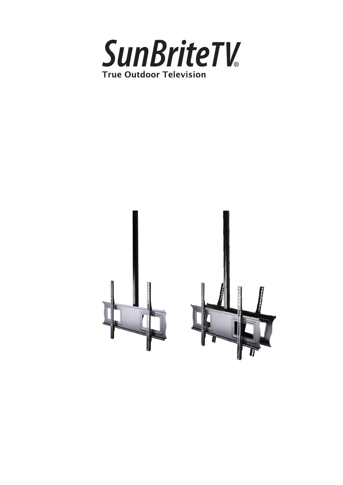
SB-CM-T-L-BL
SB-CM-DT-L-BL
Weatherproof Universal Single & Dual Ceiling Mount
for Large TVs
INSTALLATION MANUAL
Product specificaties
| Merk: | SunBriteTV |
| Categorie: | Niet gecategoriseerd |
| Model: | SB-CM-T-L-BL |
Heb je hulp nodig?
Als je hulp nodig hebt met SunBriteTV SB-CM-T-L-BL stel dan hieronder een vraag en andere gebruikers zullen je antwoorden
Handleiding Niet gecategoriseerd SunBriteTV

14 Juli 2025
18 Februari 2024
18 Februari 2024
18 Februari 2024
18 Februari 2024
18 Februari 2024
18 Februari 2024
18 Februari 2024
18 Februari 2024
18 Februari 2024
Handleiding Niet gecategoriseerd
Nieuwste handleidingen voor Niet gecategoriseerd
22 Juni 2026
22 Juni 2026
22 Juni 2026
22 Juni 2026
22 Juni 2026
22 Juni 2026
22 Juni 2026
22 Juni 2026
22 Juni 2026
22 Juni 2026