Sony NXL-FR318 Handleiding
Sony
Niet gecategoriseerd
NXL-FR318
Bekijk gratis de handleiding van Sony NXL-FR318 (3 pagina’s), behorend tot de categorie Niet gecategoriseerd. Deze gids werd als nuttig beoordeeld door 248 mensen en kreeg gemiddeld 4.8 sterren uit 124.5 reviews. Heb je een vraag over Sony NXL-FR318 of wil je andere gebruikers van dit product iets vragen? Stel een vraag
Pagina 1/3

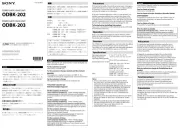
4-579-617- (1)12
Before operating the unit, please read this manual thoroughly and retain it for
future reference.
WARNING
To reduce the risk of fire or electric shock, do not
expose this apparatus to rain or moisture.
To avoid electrical shock, do not open the cabinet.
Refer servicing to qualified personnel only.
THIS APPARATUS MUST BE EARTHED.
WARNING
This unit has no power switch.
When installing the unit, incorporate a readily accessible disconnect device in
the fixed wiring, or connect the power plug to an easily accessible socket-outlet
near the unit. If a fault should occur during operation of the unit, operate the
disconnect device to switch the power supply off, or disconnect the power plug.
Attention-when the product is installed in Rack:
1. Prevention against overloading of branch circuit
When this product is installed in a rack and is supplied power from an outlet
on the rack, please make sure that the rack does not overload the supply
circuit.
2. Providing protective earth
When this product is installed in a rack and is supplied power from an
outlet on the rack, please confirm that the outlet is provided with a suitable
protective earth connection.
3. Internal air ambient temperature of the rack
When this product is installed in a rack, please make sure that the internal air
ambient temperature of the rack is within the specified limit of this product.
4. Prevention against achieving hazardous condition due to uneven
mechanical loading
When this product is installed in a rack, please make sure that the rack does
not achieve hazardous condition due to uneven mechanical loading.
5. Install the equipment while taking the operating temperature of the
equipment into consideration
For the operating temperature of the equipment, refer to the specifications of
the Operation Manual.
6. When performing the installation, keep the following space away from
walls in order to obtain proper exhaust and radiation of heat.
Right, Left : 4 cm (1.6 inches) or more
Rear : 10 cm (4 inches) or more
When installing the installation space must be secured in consideration of the
ventilation and service operation.
Do not block the ventilation slots at the left side and right side panels, and
ˎ
vents of the fans.
Leave a space around the unit for ventilation.
ˎ
Leave more than 40 cm of space in the rear of the unit to secure the operation
ˎ
area.
When the unit is installed on the desk or the like, leave at least 4 cm of space
in the left and right sides. Leaving 40 cm or more of space above the unit is
recommended for service operation.
WARNING: THIS WARNING IS APPLICABLE FOR USA ONLY.
If used in USA, use the UL LISTED power cord specified below.
DO NOT USE ANY OTHER POWER CORD.
Plug Cap Parallel blade with ground pin
(NEMA 5-15P Configuration)
Cord Type SJT, three 16 or 18 AWG wires
Length Minimum 1.5 m (4 ft 11 in), Less than 4.5 m (14 ft 9 in)
Rating Minimum 10A, 125V
Using this unit at a voltage other than 120 V may require the use of a different
line cord or attachment plug, or both. To reduce the risk of fire or electric shock,
refer servicing to qualified service personnel.
WARNING: THIS WARNING IS APPLICABLE FOR OTHER COUNTRIES.
1. Use the approved Power Cord (3-core mains lead) / Appliance Connector /
Plug with earthing-contacts that conforms to the safety regulations of each
country if applicable.
2. Use the Power Cord (3-core mains lead) / Appliance Connector / Plug
conforming to the proper ratings (Voltage, Ampere).
If you have questions on the use of the above Power Cord / Appliance
Connector / Plug, please consult a qualified service personnel.
For the customers in the U.S.A.
This equipment has been tested and found to comply with the limits for a Class A
digital device, pursuant to part 15 of the FCC Rules. These limits are designed to
provide reasonable protection against harmful interference when the equipment
is operated in a commercial environment. This equipment generates, uses,
and can radiate radio frequency energy and, if not installed and used in
accordance with the instruction manual, may cause harmful interference to radio
communications. Operation of this equipment in a residential area is likely to
cause harmful interference in which case the user will be required to correct the
interference at his own expense.
You are cautioned that any changes or modifications not expressly approved in
this manual could void your authority to operate this equipment.
All interface cables used to connect peripherals must be shielded in order to
comply with the limits for a digital device pursuant to Subpart B of part 15 of FCC
Rules.
This device complies with part 15 of the FCC Rules. Operation is subject to the
following two conditions: (1) This device may not cause harmful interference,
and (2) this device must accept any interference received, including interference
that may cause undesired operation.
For the customers in Canada
CAN ICES-3 (A)/NMB-3(A)
For the customers in Europe
This product is intended for use in the following Electromagnetic Environment:
E4 (controlled EMC environment, ex. TV studio).
This apparatus shall not be used in the residential area.
For the customers in Europe, Australia and New Zealand
WARNING
This equipment is compliant with Class A of CISPR 32. In a residential
environment this equipment may cause radio interference.
CAUTION
For safety, do not connect the connector for peripheral device wiring that might
have excessive voltage to the following port.
- NETWORK connector
Follow the instructions in this document and the installation manual for the
above port.
CAUTION
When you connect the NETWORK connector of the unit to peripheral device,
use a shielded-type cable to prevent malfunction due to radiation or static noise.
For kundene i Norge
Dette utstyret kan kobles til et IT-strømfordelingssystem.
For the customers in Taiwan only
For the customers in the U.S.A.
SONY LIMITED WARRANTY - Please visit http://www.sony.com/psa/
warranty for important information and complete terms and conditions of
Sony’s limited warranty applicable to this product.
For the customers in Canada
SONY LIMITED WARRANTY - Please visit http://www.sonybiz.ca/pro/
lang/en/ca/article/resources-warranty-product-registration for important
information and complete terms and conditions of Sony’s limited warranty
applicable to this product.
For the customers in Europe
Sony Professional Solutions Europe - Standard Warranty and Exceptions on
Standard Warranty.
Please visit http://www.pro.sony.eu/warranty for important information and
complete terms and conditions.
For the customers in Korea
SONY LIMITED WARRANTY - Please visit http://bpeng.sony.co.kr/handler/
BPAS-Start for important information and complete terms and conditions of
Sony’s limited warranty applicable to this product.
Overview
This product is a bridge device for transferring SDI input/output signals on a 4K
live production system via a network. Up to 18 optional boards that are 3 rack
units in size can be mounted in the unit.
Parts Identification
Front
1 STATUS indicator
For details, see the “Status Indicator” section.
2 BEACON indicator
This is blinks blue in sync with the beacon lamp of any optional board that is
installed on the unit.
3 Front panel LED
This lights blue when the unit is turned on (depending on settings).
Rear
1 Fan unit (A, B)
2 Power connectors (A, B)
3 Ground connector
4 REFERENCE IN connectors
5 AUX IN connector (for future expansion)
6 NETWORK connector
7 STATUS OUT connector
Outputs errors occurring on the unit or the optional boards installed on the
unit.
Installation
To use this unit, settings must be configured according to the installation
manual. For details on acquiring the installation manual, contact your local Sony
service representative.
Status Indicator
The following states of the unit are indicated by the state of the status indicator.
Indicator Status Solution
Lit green Indicates that the unit is
operating normally.
—
Blinking
orange
Indicates a warning that has
no immediate affect on normal
operation.
Example:
The replacement cycle of the
ˎ
power supply fan or on-board
fan has been reached.
The date and time
ˎ
information has been reset.
A mismatch in video input
ˎ
signal formats or a signal error
has been detected by the
optional board.
Check the cables connected to
the unit and the status of the
signals.
If the status indicator does not
light green despite a lack of
problems with the cables and
signals, contact your local Sony
service representative.
SIGNAL PROCESSING
UNIT
Operation Manual
© 2015 Sony Corporation Printed in Japan
NXL-FR318

Indicator Status Solution
Lit red Indicates that the unit is not
turned on despite the presence
of a power supply.
Example:
The CPU does not start
ˎ
properly.
Restart the unit.
If the status indicator lights
or blinks red even after the
unit is restarted, discontinue
operation of the unit and
contact your local Sony service
representative.
Blinking
red
Indicates that a critical error that
will affect normal operation has
occurred.
Example:
The unit restarted in recovery
ˎ
mode.
A temperature error has
ˎ
occurred inside the casing.
A power supply voltage error
ˎ
has occurred.
A power supply unit error has
ˎ
occurred.
A fan stop error has been
ˎ
detected.
An error that requires a unit
ˎ
restart has been detected.
A critical error has occurred
ˎ
on the optional board.
Off Indicates that power is not
being supplied or that the CPU
is not operating properly.
If the indicator is off despite the
presence of a power supply,
restart the unit.
If the status indicator remains off
even after the unit is restarted,
discontinue operation of the
unit and contact your local Sony
service representative.
Usage Precautions
Condensation
If the unit is suddenly taken from a cold to a warm location, or if ambient
temperature suddenly rises, moisture may form on the outer surface of the unit
and/or inside of the unit. This is known as condensation. If condensation occurs,
turn off the unit and wait until the condensation clears before operating the unit.
Operating the unit while condensation is present may damage the unit.
Consumable parts
The life expectancy of the electrolytic capacitor is about 5 years under normal
operating temperatures and normal usage.
The life expectancy changes depending on the usage environment.
Precautions for Network-enabled Devices
SONY WILL NOT BE LIABLE FOR DAMAGES OF ANY KIND RESULTING FROM A
FAILURE TO IMPLEMENT PROPER SECURITY MEASURES ON TRANSMISSION
DEVICES, UNAVOIDABLE DATA LEAKS RESULTING FROM TRANSMISSION
SPECIFICATIONS, OR SECURITY PROBLEMS OF ANY KIND.
Depending on the operating environment, unauthorized third parties on
the network may be able to access the unit. When connecting the unit to the
network, be sure to confirm that the network is protected securely.
From a safety standpoint, when using the unit connected with the network, it
is strongly recommended to access the Control window via a Web browser and
change the access limitation settings from the factory preset values. (Refer to the
installation manual.)
Changing the password regularly is also recommended.
Do not browse any other website in the Web browser while making settings or
after making settings. Since the login status remains in the Web browser, close
the Web browser when you complete the settings to prevent unauthorized third
parties from using the unit or harmful programs from running.
Specifications
General specifications
Power supply AC 100 V to 240 V +/–10% 50/60 Hz, dual
Power consumption
300 W
Dimensions 440 × 132 × 420 mm (17 3/8 × 5 1/4 × 16 5/8 in.) (W × H × D)
Mass Approx. 12 kg (26 lb. 7.3 oz.)
Temperature ranges
Operation guaranteed temperature: 5 °C to 40 °C (41 °F to 104 °F)
Performance guaranteed temperature: 10 °C to 35 °C (50 °F to
95 °F)
Storage temperature: –20 °C to +60 °C (–4 °F to +140 °F)
I/O specifications
REFERENCE IN
Connector BNC type (2), loop through 75 Ω
Number of lines
1 (loop through)
Signal formats
HD tri-level sync signal, black burst signal (NTSC, PAL), SYNC
signal (NTSC, PAL)
STATUS OUT
Connector D-sub 15-pin (female)
Signal formats
Open collector
NETWORK
Connector RJ-45
Number of lines
1
Signal formats
Ethernet 100Base-T compliant
AUX-IN
Connector BNC type (1)
Supplied accessories
Operation manual (1)
Optional accessories
RMM-10 rack mount bracket
Power cord (Service Parts No.: 1-557-377-11 (USA, Canada), 1-782-929-22 (EU))
Design and specifications are subject to change without notice.
This product uses μT-Kernel source code under μT-License granted by the
T-Engine Forum (www.tron.org).
Notes
Always verify that the unit is operating properly before use. SONY WILL
ˎ
NOT BE LIABLE FOR DAMAGES OF ANY KIND INCLUDING, BUT NOT LIMITED
TO, COMPENSATION OR REIMBURSEMENT ON ACCOUNT OF THE LOSS OF
PRESENT OR PROSPECTIVE PROFITS DUE TO FAILURE OF THIS UNIT, EITHER
DURING THE WARRANTY PERIOD OR AFTER EXPIRATION OF THE WARRANTY,
OR FOR ANY OTHER REASON WHATSOEVER.
SONY WILL NOT BE LIABLE FOR CLAIMS OF ANY KIND MADE BY USERS OF
ˎ
THIS UNIT OR MADE BY THIRD PARTIES.
SONY WILL NOT BE LIABLE FOR THE TERMINATION OR DISCONTINUATION
ˎ
OF ANY SERVICES RELATED TO THIS UNIT THAT MAY RESULT DUE TO
CIRCUMSTANCES OF ANY KIND.
Product specificaties
| Merk: | Sony |
| Categorie: | Niet gecategoriseerd |
| Model: | NXL-FR318 |
Heb je hulp nodig?
Als je hulp nodig hebt met Sony NXL-FR318 stel dan hieronder een vraag en andere gebruikers zullen je antwoorden
Handleiding Niet gecategoriseerd Sony
28 Juli 2025
8 Juli 2025
7 Juli 2025
7 Juli 2025
7 Juli 2025
7 Juli 2025
7 Juli 2025
7 Juli 2025
7 Juli 2025
7 Juli 2025
Handleiding Niet gecategoriseerd
- Vornado
- YSI
- Mr. Beams
- Majella
- Postium
- Prompter People
- Enviroswim
- Binatone
- Polarlite
- Caroma
- Bosch
- Creality
- Forever
- Ultimate Support
- Sonos
Nieuwste handleidingen voor Niet gecategoriseerd

31 Juli 2025
31 Juli 2025
31 Juli 2025
31 Juli 2025

31 Juli 2025
31 Juli 2025
30 Juli 2025
30 Juli 2025
30 Juli 2025
30 Juli 2025