Sonel VT-2 Handleiding


Lees hieronder de 📖 handleiding in het Nederlandse voor Sonel VT-2 (4 pagina's) in de categorie Niet gecategoriseerd. Deze handleiding was nuttig voor 12 personen en werd door 2 gebruikers gemiddeld met 4.5 sterren beoordeeld

Pagina 1/4
6 5 4 3 2 1
BEZDOTYKOWY WSKAŹNIK NAPIĘCIA
PRZEMIENNEGO -2 Z LATARVT
INSTRUKCJA OBSŁUGI
Wersja 1.03 03.07.2023
OSTRZEŻENIE
Należy przeczytać ze zrozumieniem
wszystkie informacje dotyczące bez-
pieczeństwa znajdujące się w niniej-
szej instrukcji obsługi przed rozpo-
częciem obsługi lub serwisowania
urządzenia.
1 Bezpieczeństwo
Niniejsza instrukcja obsługi oraz wszelkie oznaczenia na narzę-
dziu dostarczają informacji celem unikania zagreń i niebezpiecznych
praktyk związanych z wykorzystaniem wskaźnika. Należy przestrze-
gać wszystkich dostępnych informacji dotyczących bezpieczeństwa.
OSTRZEŻENIE
Należy przeczytać instrukcję ze zro-
zumieniem przed rozpoczęciem ob-
sługi. Brak zrozumienia w zakresie
bezpiecznej obsługi może spowodo-
wać wypadek lub śmierć.
OSTRZEŻENIE
Niebezpieczeństwo porażenia prą-
dem - kontakt z obwodami pod na-
pięciem może spowodowpoważne
obrażenia lub śmierć.
OSTRZEŻENIE
Niebezpieczeństwo porażenia prą-
dem:
Nie używać urządzenia, jeśli jest
mokre lub uszkodzone.
Nie stosować przy napięciu zna-
mionowym wszym niż dopusz-
czalne pomiędzy końcówką sondy
i uziemieniem.
Nie korzystać, gdy obudowa jest
otwarta.
Nieprzestrzeganie tych ostrzeż
może doprowadzić do poważnych
obra żeń lub śmierci.
OSTRZEŻENIE
Nie należy próbować naprawiać
urządzenia, gdyż nie zawiera ono
części, które mogą być serwiso-
wane przez użytkownika.
Nie wystawiać urządzenia na dzia-
łanie wysokich temperatur lub wil-
goci (patrz specykacja).
Nieprzestrzeganie tych ostrzeż
może doprowadzić do poważnych
obrażeń lub śmierci oraz uszkodze-
nia urządzenia.
2 Cechy
Bezdotykowe wykrywanie napięcia przemiennego w zakresie
90...1000 V (50/60 Hz).
Wytrzymała dwukomponentowa obudowa.
do wykrywania przerw w instalacji lub Możliwość stosowania
obecności napięcia w gniazdach, lampach, wyłącznikach,
przewodach i kablach.
Jasny sygnał świetlny diody LED i dźwiękowy, gdy obecne jest
napięcie.
Wbudowana latarka z przyciskiem ON/OFF.
Wygodny kieszonkowy rozmiar z zaczepem.
Niezbędne narzędzie dla każdego elektryka i montera.
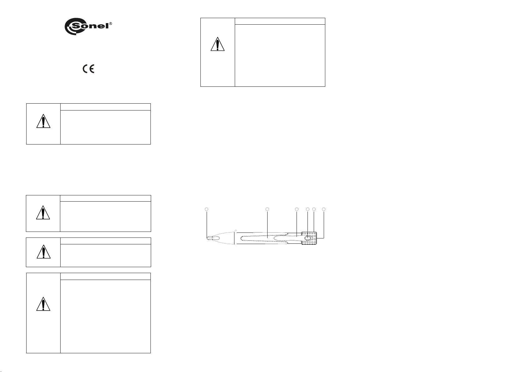
3 Opis
-2 jest przeznaczony do sygnalizowania Wskaźnik napięcia VT
obecności napięcia AC za pomocą diody LED i dźwięk u. Posiada
wbudowaną latarkę z przyciskiem ON/OFF.
Latarka
Uchwyt wskaźnika
Włącznik/Wyłącznik latarki ON/OFF
Klips
Obudowa wskaźnika
Końcówka wskaźnika
4 Działanie
Wskaźnik napięcia stosuje się do wykrywania przewodów fazo-
wych, przerw w przewodach i obecności napięcia AC w:
gniazdach,
przełącznikach,
nikach, wyłącz
bezpiecznikach,
przewodach i kablach.
Uwaga: Wskaźnik napięcia może zostać użyty do wykrycia przerwy w prze-
wodzie:
do znalezienia przerwy w przewodzie fazowym: obserwować przewód do
momentu zaniku sygnału,
do znalezienia przerwy w przewodzie neutralnym: podłączyć obciążenie
pomiędzy przewód fazowy a neutralny. Obserwować przewód do momentu
zaniku sygnału.
5 Obsługa
Przed użyciem należy przetestować urządzenie na znanym działa-
jącym obwodzie lub urządzeniu:
iwaniami na Jeżeli urządzenie nie działa zgodnie z oczek
znanym i działającym obwodzie, należy wymienić baterie.
Jeżeli urządzenie nadal nie funkcjonuje zgodnie z oczekiwa-
niami, należy wysłać urządzenie do naprawy.
Umieścić końcówkę sondy na lub w pobliżu obwodu lub urządze-
nia do testowania. Świecenie diody LED i sygnał dźwiękowy
wskazują obecność napięcia przemiennego od 90…1000 V AC
(50/60 Hz).
Uwaga:
Wskaźnik napięcia nie wykrywa napięcia w kablach zbrojonych lub kablach
w kanale, za metalowymi panelami lub w metalowych obudowach.
Wskaźnik może reagować na wolnozmienne pole elektrostatyczne, np. nae-
lektryzowane materiały.
Wskaźnik może pokazywać obecność napięcia w dalszej odległości od ba-
danego obiektu, w przypadku dużego nagromadzenia obiektów pod napię-
ciem w pobliżu (np. skrzynki kablowe).
6 Wymiana baterii
1. Odłączyć urządzenie od obwodu.
2. Odgiąć klips (4) i ściągnąć uchwyt wskaźnika przesuwając go (2)
w prawo (względem rysunku obok).
3. Wymienić baterie (błędna polaryzacja może uszkodzić wskaźnik).
4. Założyć pokrywę na komorę baterii.
7 Specykacja techniczna
Urządzenie nie posiada charakteru wzorca i dlatego nie podlega
wzorcowaniu. Właściwą formą kontroli dla tego typu przyrządów
jest sprawdzenie.
a) Wskaźniki.......................... dioda LED i sygnalizator dźwiękowy
b) Zakres napięcia................................. 90...1000 V AC (50/60 Hz)
c) Kategoria przepięciowa ....................................... CAT III 1000 V
d) Stopień zanieczyszczenia........................................................ 2
e) obudowy Stopień ochrony .................................................. IP54
f) Temperatura pracy ................................................. - 0 C 10…+5 °
g) do 80% bez kondensacji Wilgotność...........................................
h) Bateria ......... 2 x 1,5 V (baterie AAA, NEDA 24A lub IEC LR 03)
i) Wymiary ........................ 177 mm (długość), Φ27 mm (przekrój)
j) Waga....................................................... ok. g (bez baterii) 100
k) Latarka .......................................................... biała z diodą LED
Wyprodukowano w Chińskiej Republice Ludowej
na zlecenie SONEL S.A.
6 5 4 3 2 1
NON-CONTACT AC VOLTAGE DETECTOR
WITH FLASHLIGHT -2 VT
USER MANUAL
Version 1.03 03.07.2023
WARNING
Read understand all of the iand n-
structions and safety information in
this manual before operating or ser-
vicing this tool.
1 Safety
This instruction manual and any markings on the tool provide in-
formation for avoiding hazards and unsafe practices related to the
use of this tool. Observe all of the safety information provided.
WARNING
Read and understand this material
before operating or servicing this
equipment. Failure to understand how
to safely operate this tool can result in
an accident causing serious injury or
death.
WARNING
Electric shock hazard - contact with
live circuits can result in severe injury
or death.
WARNING
Electric shock hazard:
Do not use the unit if it is wet or
damaged.
Do not apply more than the rated
voltage between the probe tip and
earth ground.
Do not operate with the case
open.
Failure to observe these warning can
result in severe injury or death.
WARNING
Do not attempt to repair this unit. It
contains no user-serviceable
parts.
Do not expose the unit to ex-
tremes in temperature or high hu-
midity (see specications).
Failure to observe these precautions
can result in injury and can damage
the instrument.
2 Features
Non-contact detection of AC Voltage 90…1000 V (50/60 Hz).
Rugged, double molded case.
May be used to nd a break in a wire or detect the presence of
voltage at outlets, lighting xtures, circuit breakers, wires and
cables.
Bright LED and audible beeper indica r if voltage is present. to
Built-in bright ashlight with ON/OFF button.
Convenient size with pocket clip.
An essential tool for every electrician and tradesperson.
3 Detector description
The VT-2 voltage detector is intended to signal the presence of
AC voltage with an LED on and an acoustic notication. Built-in
bright ashlight with ON/OFF button and audible beeper indicator.
Flashlight
Detector handle
Flashlight power ON/OFF
Detector clip
Detector body
Detector cap
4 Operation
The Voltage Detector is useful for the identifying phase conduc-
tors, finding a break in a wire and detecting the presence of AC volt-
age at:
outlets,
switches,
circuit breakers,
fuses,
wires and cables.
Note: The voltage detector can be used to nd a break in a wire:
to nd a break in a phase conductor, trace the wire until the signal
stops,
to nd a break in a neutral conductor, connect a load between the
phase and neutral. Trace the wire until the signal stops.
5 Operating of voltage detector
Test the unit on known f tioning circuit or component: unc
If the unit does not function as expected on a known func-
tioning circuit, replace the batteries.
If the unit still does not function as expected, send the unit to
repair.
Place the probe tip on or near the circuit or unit to be tested. LED
and audible beeper indicate the presence of AC Voltage from
90…1000 V (50/60 Hz).
Note:
The voltage detector cannot detect voltage on armored cable or on
cable in conduit, behind panels or in metallic enclosures.
The detector can react to extremely low frequency electrostatic
eld, such as electried materials.
The detector can show the presence of voltage at a greater di-
stance from the object, in the case of high concentration of live ob-
jects in the near to measured object (eg. circuits box).
6 Battery replacement
1. Disconnect the unit from the circuit.
2. Fold back the clip (4) and remove detector handle (2) by moving it
to the right side (according to the picture).
3. Replace the batteries (wrong polarity of batteries may damage de-
tector).
4. Put the battery compartment cover.
7 Technical specications
The device does not have the character of a standard and therefore
is not subject to calibration. The proper form of control for this type of
instrument is checking.
a) Indicators LED and audible beeper ............................................
b) ange Voltage r .................................. 90…1000 V AC (50/60 Hz)
c) Overvoltage category ......................................... CAT III 1000 V
d) egree Pollution d ...................................................................... 2
e) Ingress protection .............................................................. IP 54
f) Operating temperature ........................................... -10…+5 °0 C
g) Humidity ........................................... 80% without condensation
h) Battery ........ 2 x 1,5 V batteries (AAA, NEDA 24A or IEC LR 03)
i) Dimensions ..................... mm (length), mm (diameter) 177 Φ27
j) Weight ..................................... approx. 100 (without batteries) g
k) Flashlight ............................................................ one white LED
6 5 4 3 2 1
DETECTOR DE TENSIÓN SIN CONTACTO
CON LINTERNA VT-2
MANUAL DE USO
Versión 1.03 03.07.2023
AVISO
Lea detenidamente este manual de
instrucciones antes de utilizar el
equipo.
1 Seguridad
Este manual de instrucciones las advertencies en el propio
equipo proporcionan información para evitar practica
peligrosas relacionadas con el uso de este equipo. Lea toda la
información de seguridad proporcionada.
AVISO
Lea detenidamente este manual de
instrucciones antes de utilizar el
equipo. Un error en el uso del equipo
puede provocar un accidente grave.
AVISO
Peligro de electrocución el contacto
con circuitos en tensión puede
provocar heridas o la muerte.
AVISO
Peligro de electrocución:
No use el equipo si está humedo o
dañado.
No apliqué mas tension de la que
el equipo puede soportar según
sus especicaciones entre la
punta reprueba y tierra.
No usar con la carcasa abierta.
El no seguimiento de estas
advertencias puede provocar heridas
severas o la muerte.
AVISO
No intente reparar el equipo. Con-
tiene partes no reparables.
No exponga al equipo a
temperaturas extremas o alta
humedad (ver especicaciones).
El no seguimiento de estas
advertencias puede provocar heridas
severas o la muerte.
2 Caracteristicas
Detección de tension alterna sin contacto 90…1000 V
(50/60 Hz).
Envolvente rigida.
P ser utilizado para localizar un corte en un cable o uede
detectar la presencia de tension en enchufes o tomas de
corriente, accesorios de iluminación, interruptores
magnetotermicos y cables.
Indicador acustico y luminoso LED en caso de presencia de
tensión.
Incluida linterna con boton ON/OFF.
Tamaño pequeño con clip para colgar.
Una herramienta esencial para cualquier instalador.
3 Descripción del detector
El detector de tensión - tiene como function principal la de VT 2
detector la presencia de tension alterna, con señalización
acustica y luminosa LED. Ademas incorpora una linterna con
boton ON/OFF.
Linterna
Sujección del detector
Boton ON/OFF de la linterna
Clip del detector
Cuerpo del detector
Capuchón del detector
4 Funcionamiento
El detector de tension es usado para identicar conductores
de fase, localizador de roturas de cables y detector la tension
alterna en:
enchufes,
interruptores,
interruptores magnetotermicos ,
fusibles,
cables.
Nota: El detector de tension puede ser utilizado para localizar una rotura en
un cable:
para encontrar la rotura en un conductor de fase, trazar el cable hasta que
la señal se detenga.
para encontrar la rotura en un conductor neutron, conectar una carga entre
la fase y el neutron. Trazar el cab le hasta que la señal se detenga.
5 Funcionamiento del detector
Compruebe el equipo en un circuito en funcionamiento conocido:
Si el equipo no funciona como se espera, reemplace las
baterias.
Si todavía no funciona como se espera, contacte con el
servicio técnico para su reparación.
Coloque la punta de prueba en o cerca de un circuito o equipo
para ser comprobado. El avisador LED luminoso y el beep
acustico indica la presencia de tension alterna en el rango
90…1000 V (50/60 Hz).
Nota:
El detector de tension no puede detector tension en cables con pantalla o
en cables que circulan pir conductos, panels o envolventes metalicas.
El detector puede reaccionar antes campos electroestaticos de baja
frecuencia, así como materiales electrificados.
El detector puede señalizar la presencia de tension a gran distancia del
objeto, en el caso de una alta concentración de equipos en tension cerca
del objeto a medir.
6 Reemplazo de baterias
1. Desconecte el equipo de cualquier circuito.
2. Repliegue el clip (4) y extraiga la zona de sujección del detector
(2) moviendolo a la derecha (según el dibujo).
3. Reemplace las baterias (una polaridad erronea puede dañasr el
detector).
4. Coloque la tapa del compartimento de las baterias de Nuevo.
7 pecicaciones Es técnicas
El dispositivo no tiene el carácter de un patrón, por lo tanto, no está
sujeto a . La forma adecuada de control para este tipo de calibración
instrumento es la verificación.
a) Indicadores LED y beep acustico ................................................
b) Rango de tensión ............................ 90…1000 V AC (50/60 Hz)
c) Categoría de sobretensión ................................. CAT III 1000 V
d) Grado de polución ................................................................... 2
e) Grado de protección ........................................................... IP54
f) Temperatura de funcionamiento ............................. -10…+5 °0 C
g) Humedad ............................................... 80% sin condensación
h) Baterias ...................... 2 x 1,5 V (AAA, NEDA 24A o IEC LR 03)
i) Dimensiones mm (largo), mm (diametro) ..................... 177 Φ27
j) Peso ................................................. aprox. 100 as) g (sin baterí
k) Linterna .............................................................. LED blanco un


Product specificaties

Merk: Sonel
Categorie: Niet gecategoriseerd
Model: VT-2

Heb je hulp nodig?

Als je hulp nodig hebt met Sonel VT-2 stel dan hieronder een vraag en andere gebruikers zullen je antwoorden


Handleiding Niet gecategoriseerd Sonel

Handleiding Niet gecategoriseerd

Nieuwste handleidingen voor Niet gecategoriseerd