Silent Knight SD500-MIM Handleiding
Silent Knight
Detector
SD500-MIM
Bekijk gratis de handleiding van Silent Knight SD500-MIM (2 pagina’s), behorend tot de categorie Detector. Deze gids werd als nuttig beoordeeld door 43 mensen en kreeg gemiddeld 3.6 sterren uit 22 reviews. Heb je een vraag over Silent Knight SD500-MIM of wil je andere gebruikers van dit product iets vragen? Stel een vraag
Pagina 1/2

P/N 151071
SD500-AIM Input Module and
SD500-MIM Mini Input Module
Installation Instructions
The following instructions are a quick reference
guide, refer to the control panel installation
manual P/N 151139, 151274, 151280, 151295,
151209, or 151302 for detailed system
information.
Wiring the SD500-AIM / MIM
Note: Installation and wiring of these devices must be done in
accordance with NFPA 72 and local ordinances.
Terminate the wiring as shown in Table 1. See
also Figure 1 or Figure 2
Specifications
Table 2 lists the operating specifications for the
SD500-AIM and the SD500-MIM.
Impedance for Earth Ground Fault is 0 Ω for all
terminals.
Figure 1: Class B Wiring the SD500-AIM & SD500-MIM
Table 1: Wire Connections
SD500-AIM
SD500-MIM
Terminals
To:
FACP or SLC
Loop Terminals Contact
SLC –SLC
OUT
SC–
+ S+
Contact
A out CLASS A
OR B
To N.O. Contact
B out To N.O. Contact
A IN CLASS A ONLY
(SD500-AIM Only)
End of Loop A
End of Loop B
B IN
Table 2: SD500-AIM and SD500-MIM Specifications
Specifications
Max. Line resistance 50Ω
Max. Alarm
Current
One device in alarm
23mA. 46 mA for two
devices in alarm.
.5 mA for each addi-
tional device in
alarm.
Max. Voltage 33 V
Operating Temperature 0° to 49° C
(32° to 120° F)
Indoor use only
Table 2: SD500-AIM and SD500-MIM Specifications
Specifications
Alternate
Construction

SD500-AIM Input Module and SD500-MIM Mini Input Module Installation Instructions
2
7550 Meridian Circe, Suite 100
Maple Grove, MN 55369-4927
763-493-6455 or 800-328-0103
Fax: 763-493-6475
www.silentknight.com
© 2008 Honeywell International Inc. PN 151071 Rev G
Figure 2: Class A Wiring the SD500-AIM
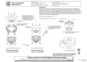
Mounting the SD500-AIM
Mount the SD500-AIM into a double gang box
as shown in Figure 3.
Mounting the SD500-MIM
Install the SD500-MIM into a single gang box
see Figure 1 and Figure 3.
Figure 3: Mounting the SD500-AIM and SD500-MIM
Setting the Devices Address
The range of valid addresses is 1 - 127 (0 is an
invalid address). Refer to Figure 4 to set the dip
switches to the desired address.
Figure 4: Setting the Device Address:
Note: The dip switch settings shown in Figure 4 apply to the
SD500-MIM also.
Status LED
Product specificaties
| Merk: | Silent Knight |
| Categorie: | Detector |
| Model: | SD500-MIM |
| Gewicht: | 45.4 g |
| Breedte: | 38 mm |
| Diepte: | 18 mm |
| Hoogte: | 64 mm |
| Aantal per verpakking: | 1 stuk(s) |
Heb je hulp nodig?
Als je hulp nodig hebt met Silent Knight SD500-MIM stel dan hieronder een vraag en andere gebruikers zullen je antwoorden
Handleiding Detector Silent Knight

15 Februari 2024

15 Februari 2024

14 Februari 2024

14 Februari 2024

14 Februari 2024

9 Februari 2024
Handleiding Detector
- Chauvin Arnoux
- Winland
- SureCall
- Astralpool
- Ebode
- Fluke
- STI
- Gossen
- Pentatech
- Pioneer
- Siedle
- HT Instruments
- Trotec
- Smartwares
- Topex
Nieuwste handleidingen voor Detector
1 September 2025

20 Augustus 2025
18 Augustus 2025

12 Augustus 2025

11 Augustus 2025
11 Augustus 2025

11 Augustus 2025
8 Augustus 2025

28 Juli 2025
24 Juli 2025