SIIG CE-MT0812-S1 Handleiding
Bekijk gratis de handleiding van SIIG CE-MT0812-S1 (8 pagina’s), behorend tot de categorie Wandsteun. Deze gids werd als nuttig beoordeeld door 65 mensen en kreeg gemiddeld 4.0 sterren uit 8 reviews. Heb je een vraag over SIIG CE-MT0812-S1 of wil je andere gebruikers van dit product iets vragen? Stel een vraag
Pagina 1/8
04-0541A
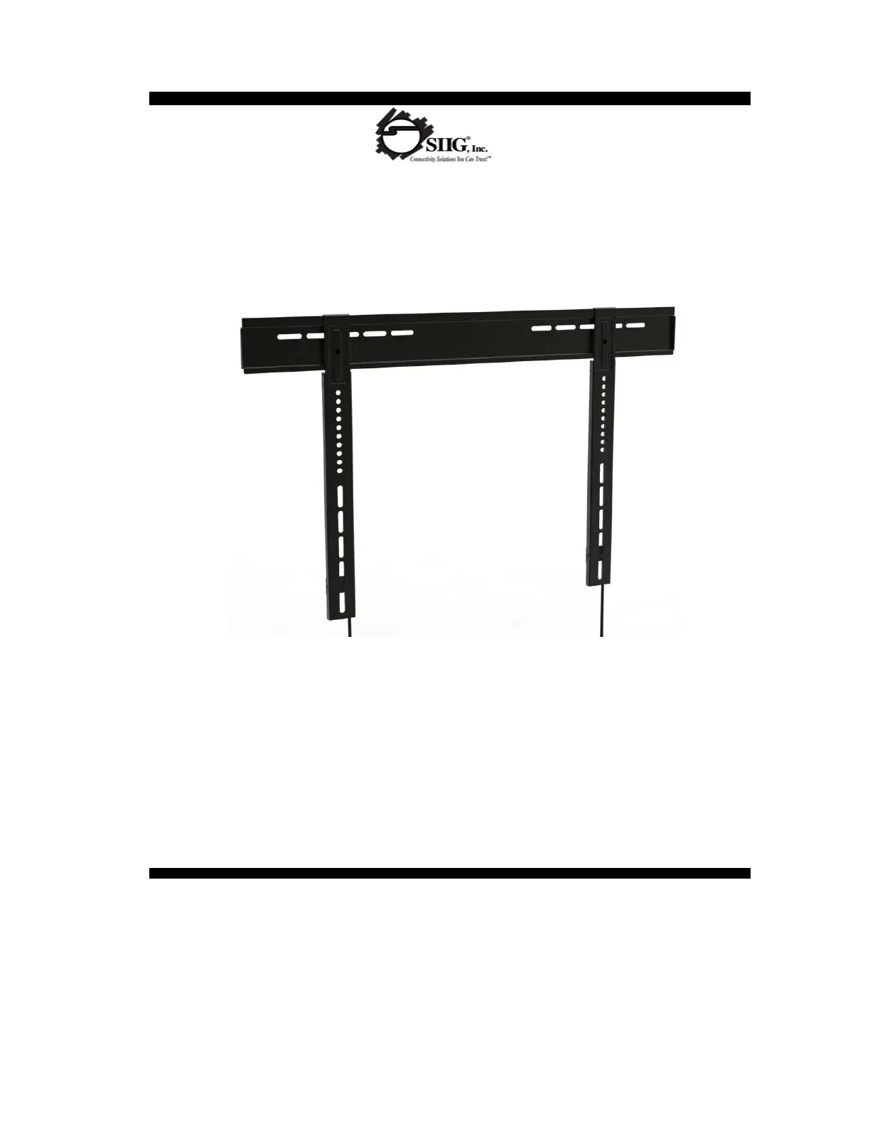
TV Size: 32" - 55”
Max load capacity: 121lbs/55kg
Wall distance: 0.43/11mm
Universal Mounting Pattern
Ultra-Thin LED/LCD TV Mount - 32" to 55"
IMPORTANT: If you don't understand the installation instructions, please consult an
installation specialist
Ultra-Thin LED/LCD TV Wall Mount
Material: 2.0mm Cold Rolled Steel Plate
Installation Instructions
1
Product specificaties
| Merk: | SIIG |
| Categorie: | Wandsteun |
| Model: | CE-MT0812-S1 |
| Kleur van het product: | Zwart |
| Breedte: | 750 mm |
| Diepte: | 11 mm |
| Hoogte: | 545 mm |
| Materiaal behuizing: | Staal |
| Montagewijze: | Muur |
| Geschikt voor schermmaten: | 32 - 55 " |
| Maximale gewichtscapaciteit: | 60 kg |
| Certificering: | UL |
| Paneelmontage-interface: | 200 x 100,200 x 200,600 x 200,600 x 400 mm |
| Compatibiliteit: | LED/LCD TV |
| Montage interface compatibiliteit (min): | 200 x 100 mm |
| Montage interface compatibiliteit (max): | 600 x 400 mm |
Heb je hulp nodig?
Als je hulp nodig hebt met SIIG CE-MT0812-S1 stel dan hieronder een vraag en andere gebruikers zullen je antwoorden
Handleiding Wandsteun SIIG

28 Juni 2025
13 Maart 2024
13 Maart 2024
13 Maart 2024
13 Maart 2024
13 Maart 2024
13 Maart 2024
12 Maart 2024
12 Maart 2024
12 Maart 2024
Handleiding Wandsteun
Nieuwste handleidingen voor Wandsteun
16 Juli 2026
16 Juli 2026
15 Juli 2026
14 Juli 2026
14 Juli 2026
13 Juli 2026
13 Juli 2026
12 Juli 2026
9 Juli 2026
8 Juli 2026