Sauermann Si-DPMS Handleiding
Sauermann Niet gecategoriseerd Si-DPMS
Bekijk gratis de handleiding van Sauermann Si-DPMS (4 pagina’s), behorend tot de categorie Niet gecategoriseerd. Deze gids werd als nuttig beoordeeld door 42 mensen en kreeg gemiddeld 4.4 sterren uit 9 reviews. Heb je een vraag over Sauermann Si-DPMS of wil je andere gebruikers van dit product iets vragen? Stel een vraag
Pagina 1/4
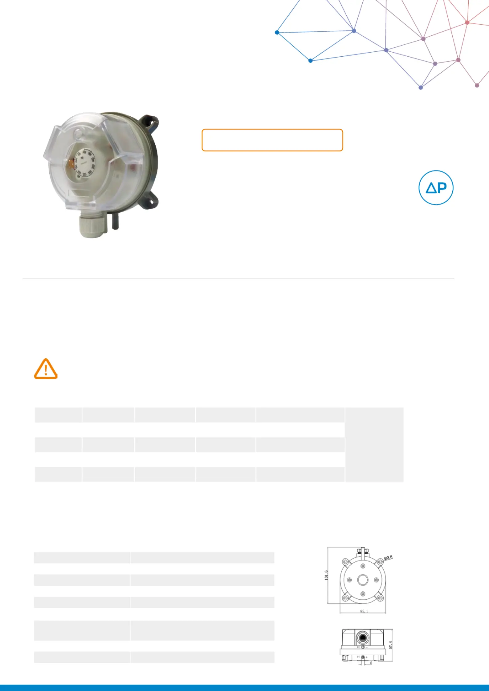
Si-DPMS
Differential Pressure Switches
USER MANUAL
Presentation
The differential air pressure switches with membrane are used for the control of air treatment system installations. They allow, without
supply, to establish a switching contact during a cut-off pressure exceeding. They can be mounted in parallel with a manometer.
They allow to control systems working under or over pressure, fans or lter.
Description
Before the commissioning of the pressure switch, please read carefully this user manual.
*
Pressure values referred to vertical installation. If the device is installed horizontally, these values increase by 20 Pa.
The differential pressure switches have a round shape and two connections of Ø 6.2 mm (for hoses, of Ø 5 x 8 mm for example).
They are supplied with the needed installation accessories.
General features
MediaAir, non-combustible and non-aggressive gases
Maximum pressure10 kPa
Voltage250 V / 1.5 A (0.4 A)
Mounting Vertical
ProtectionIP54 (with cover), IP00 (without cover)
Operating temperature-40 °C to 85 °C
Relay typeSPDT
Electrical rating
Resistance: initial: < 50 mΩ
Current: 1.5 A (0.4 A) / 250 V
Contact terminals6.3 mm x 0.8 mm blade or screw terminal
ConnectionØ 6.0 mm for tube connection
CerticationCE
Dimensions (mm)
Model
Measuring
range (Pa)*
High point
tolerance
Switching
differential (Pa)
Tolerance of switching
differential (Pa)
Max Pressure
(Pa)
Si-DPMS-120 - 200±15%10±5
10 000
Si-DPMS-250 - 500±15%20±10
Si-DPMS-3200 - 1000±15%100±20
Si-DPMS-4500 - 2500±15%150±40
Si-DPMS-51000 - 5000±15%250±70
Product specificaties
| Merk: | Sauermann |
| Categorie: | Niet gecategoriseerd |
| Model: | Si-DPMS |
Heb je hulp nodig?
Als je hulp nodig hebt met Sauermann Si-DPMS stel dan hieronder een vraag en andere gebruikers zullen je antwoorden
Handleiding Niet gecategoriseerd Sauermann

14 September 2025
2 September 2025
1 September 2025
1 September 2025
1 September 2025
1 September 2025
1 September 2025
1 September 2025
1 September 2025
15 Augustus 2025
Handleiding Niet gecategoriseerd
Nieuwste handleidingen voor Niet gecategoriseerd
23 Juli 2026
23 Juli 2026
23 Juli 2026
22 Juli 2026
22 Juli 2026
22 Juli 2026
22 Juli 2026
22 Juli 2026
22 Juli 2026
21 Juli 2026