Sauermann ECM Handleiding
Bekijk gratis de handleiding van Sauermann ECM (9 pagina’s), behorend tot de categorie Niet gecategoriseerd. Deze gids werd als nuttig beoordeeld door 3 mensen en kreeg gemiddeld 4.8 sterren uit 2 reviews. Heb je een vraag over Sauermann ECM of wil je andere gebruikers van dit product iets vragen? Stel een vraag
Pagina 1/9

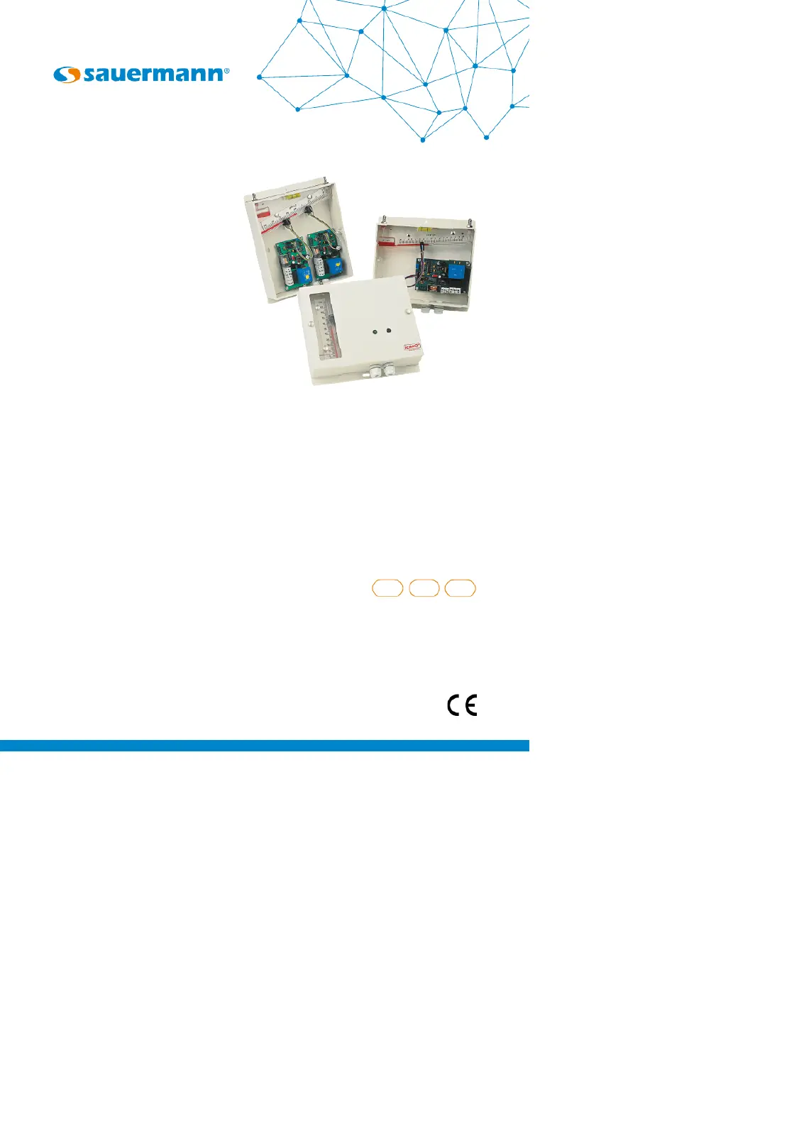
ECM - ELECTRIC CONTACT
PRESSURE CONTROLLERS
Quick Start Guide
EN FR
www.sauermanngroup.com
ES

English
Quick start guide
The ECM electric contact pressure controllers are the result of a long experience in
the research and manufacture of measuring and control instruments.
They are designed to combine the inherent reliability and accuracy of the liquid
column manometer with electronic switching.
The Sauermann electric contact pressure controllers excel where it is necessary ECM
to monitor small variations in low pressures of air or gas.
1 Operation
The ECM can be tted to a vertical or inclined manometer. The photo electric sensor
is connected to a PCB by an optical bre.
When energised the PCB generates an infra-red ray which travels along the optic
bre and throught the manometers liquid column.
The PCB senses when the liquid column breaks the infra-red ray and operates the
switch either making or breaking the contact depending on how it is set.
The ECM can operate on rising or falling pressure by changing the position of the
“inverter switch” on the PCB.
Diagrams 1 and 2 show the operation principle. The switch operates when the
pressure rises and the manometer liquid breaks the infra-red ray at 100 mm H
2
O
also lighting the LED.
When the inverter microswitch is operated (diagram 2) the switch operates when
the pressure falls and the infra-red ray is re-established at 100 mm H
2
O.
The changeover relay enables the power to be switched on or off with a delay of
up to 45 seconds. Multiple units can be tted to one manometer column to perform
different functions.

4 Connection
5 Detection sensitivity setting
The detection sensitivity of the photoelectric cursor is adjusted in the factory.
After lling the manometer, with the correct density manometer liquid, it is recommended
that you check this setting before putting the unit into service.
PROCEDURE:
Apply the voltage to the electronic card, but do not conect the relay. Turn the temporising
potentiometer to zero (fully anti-clockwise) and put the function inverterswitch to the
“normal” position (Figure 1 shows the switch in the “inverted” position).
The unit can then be operated by tilting the unit to the right, causing the manometer
liquid to pass the cursor.
CHECK PCB
RATING
In 24 Vdc
4: +
5: -
6: NC
In 24 Vac
4: connection
5: connection
6: NC
In 230 Vac / 115 Vac
4: phase
5: neutral
6: earth
1- NC
2- Common: 220 V/3 A
3- NO
4- Card power
5- Card power
6- Earth
Figure 2
Potentiometer
(25 rot.)
Function inverter
switch
Temporizing setting
Red LED
Transformer
Safety fuse
Power terminal
block
Relay terminal blockRelay
Male connection
with a mistake
corrector for cursor
Figure 1
Product specificaties
Merk: | Sauermann |
Categorie: | Niet gecategoriseerd |
Model: | ECM |
Heb je hulp nodig?
Als je hulp nodig hebt met Sauermann ECM stel dan hieronder een vraag en andere gebruikers zullen je antwoorden
Handleiding Niet gecategoriseerd Sauermann
14 Augustus 2025
14 Augustus 2025
14 Augustus 2025
14 Augustus 2025
14 Augustus 2025
14 Augustus 2025
14 Augustus 2025
14 Augustus 2025
14 Augustus 2025
14 Augustus 2025
Handleiding Niet gecategoriseerd
- GR Bass
- Ugears
- Nintendo
- Point 65
- Chief
- Speed-Link
- L.R.Baggs
- Cyrus
- Atlantic
- Targus
- Deltaco Gaming
- Digigram
- Bontempi
- OXI Instruments
- DutchOne
Nieuwste handleidingen voor Niet gecategoriseerd
14 Augustus 2025
14 Augustus 2025
14 Augustus 2025
14 Augustus 2025
14 Augustus 2025
14 Augustus 2025
14 Augustus 2025
14 Augustus 2025
14 Augustus 2025
14 Augustus 2025