Sauermann COST-S Handleiding
Sauermann Niet gecategoriseerd COST-S
Bekijk gratis de handleiding van Sauermann COST-S (4 pagina’s), behorend tot de categorie Niet gecategoriseerd. Deze gids werd als nuttig beoordeeld door 26 mensen en kreeg gemiddeld 4.9 sterren uit 6 reviews. Heb je een vraag over Sauermann COST-S of wil je andere gebruikers van dit product iets vragen? Stel een vraag
Pagina 1/4
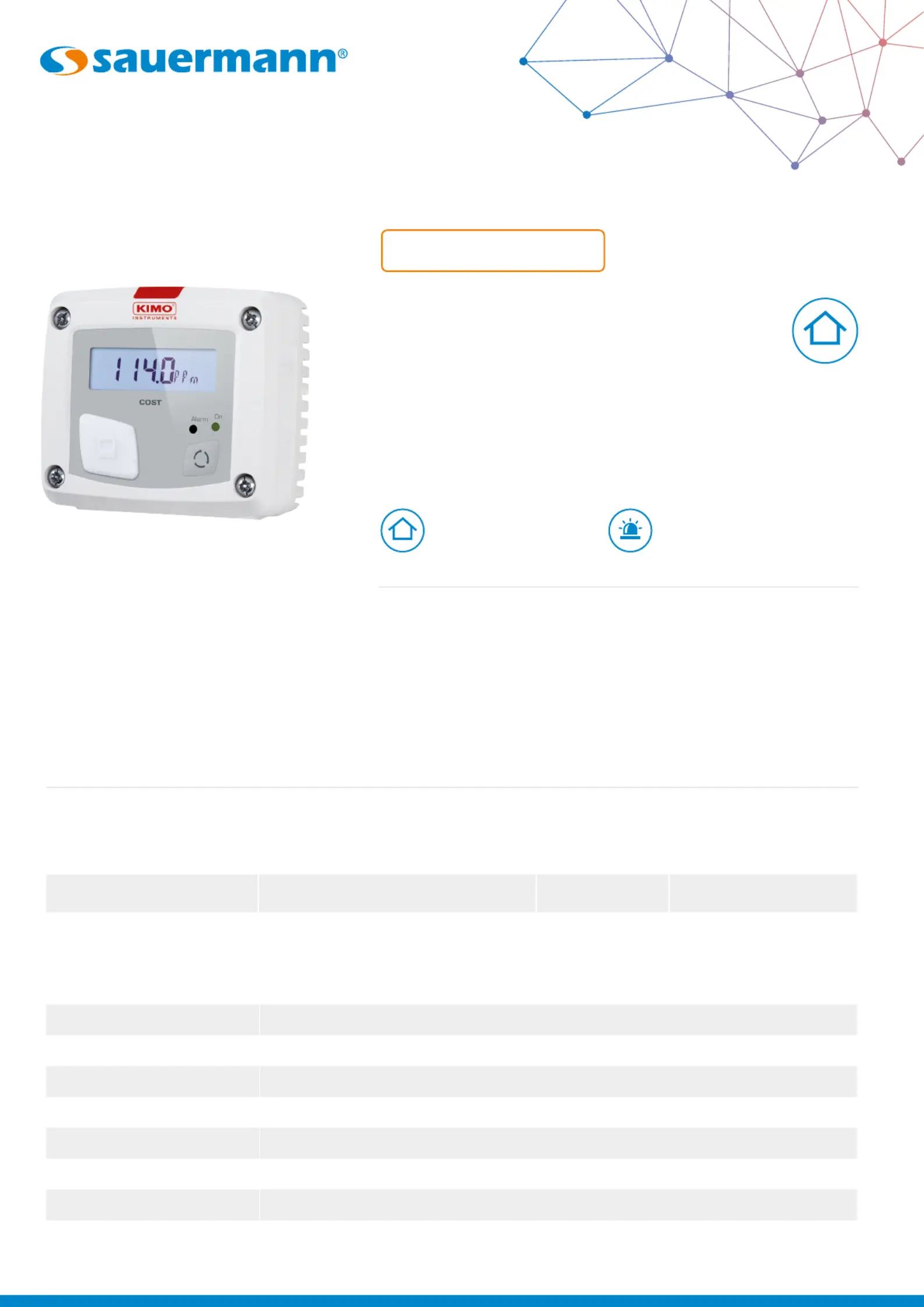
COST-S
CO Stats
CO detector
DATA SHEET
ParameterAccuracyMeasuring rangeResolution*
CO±3 ppm or 3% of the reading valueFrom 0 to 500 ppm0.1 ppm
Technical features
*All the accuracies indicated in this technical datasheet were stated in laboratory conditions, and can be guaranteed for measurements carried out in the same conditions, or carried out with calibration compensation.
Features
• RCR relay output,
3 A / 240 Vac (NC),
power supply 24 Vac/Vdc
• ABS V0 IP20 housing
• “¼ turn” system mounting
with wall-mount plate
• Housing with simplied
mounting system
Visual and audible alarm,
red led in front
Measuring range
from 0 to 500 ppm
CO
CO
Output1 RCR relay. NO (normally opened): 5A / NC (normally closed): 3A / 240 Vac.Common mode voltage <30 Vac
Power supply24 VAC/VDC ±10%
Consumption3 VA
Relay and alarm statusRed led in front and internal buzzer (70 dB at 10 cm)
European directives2014/30/EU EMC; 2014/35/EU Low Voltage; 2011/65/EU RoHS II; 2012/19/EU WEEE
Electrical connectionTerminal block for cables Ø0.05 to 2.5 mm
2
. Carried out according to the code of good practice
PC communicationUSB-mini Din cable
EnvironmentAir and neutral gas
Measured parameter
Product specificaties
| Merk: | Sauermann |
| Categorie: | Niet gecategoriseerd |
| Model: | COST-S |
Heb je hulp nodig?
Als je hulp nodig hebt met Sauermann COST-S stel dan hieronder een vraag en andere gebruikers zullen je antwoorden
Handleiding Niet gecategoriseerd Sauermann

14 September 2025
2 September 2025
1 September 2025
1 September 2025
1 September 2025
1 September 2025
1 September 2025
1 September 2025
1 September 2025
15 Augustus 2025
Handleiding Niet gecategoriseerd
Nieuwste handleidingen voor Niet gecategoriseerd
23 Juli 2026
23 Juli 2026
23 Juli 2026
22 Juli 2026
22 Juli 2026
22 Juli 2026
22 Juli 2026
22 Juli 2026
22 Juli 2026
21 Juli 2026