Sanus VMPO1 Handleiding
Sanus Flat panel steun VMPO1
Bekijk gratis de handleiding van Sanus VMPO1 (8 pagina’s), behorend tot de categorie Flat panel steun. Deze gids werd als nuttig beoordeeld door 177 mensen en kreeg gemiddeld 4.9 sterren uit 8 reviews. Heb je een vraag over Sanus VMPO1 of wil je andere gebruikers van dit product iets vragen? Stel een vraag
Pagina 1/8
Assembly Instructions for Model: VMPO
Thank You for your purchase of a Sanus Systems Vision Mount! The VMPO is designed to securely attach a Flat Panel LCD to a cabinet
or an armoire. It will allow the ability to pull the TV out and swivel. It can also be used with a VM200 for tilting LCDs or a VMPL50
for Plasmas.
Safety Warning:If you do not understand these directions, or have any doubts about the safety of the installation, please call a qualified
contractor or contact Sanus at 800.359.5520 or www.sanus.com. Check carefully to make sure that there are no missing or defective
parts. Our customer service representatives can quickly assist you with installation questions and missing or damaged parts. Replace-
ment parts for products purchased through authorized dealers will be shipped directly to you. Never use defective parts. Improper instal-
lation may cause damage or serious injury. Do not use this product for any purpose that is not explicitly specified by Sanus Systems.
Sanus Systems can not be liable for damage or injury caused by incorrect mounting, incorrect assembly, or incorrect use. Please call
Sanus Systems before returning products to the point of purchase.
Required Tools: Drill, 1/4” Drill Bit, wrench or socket set, phillips screw driver
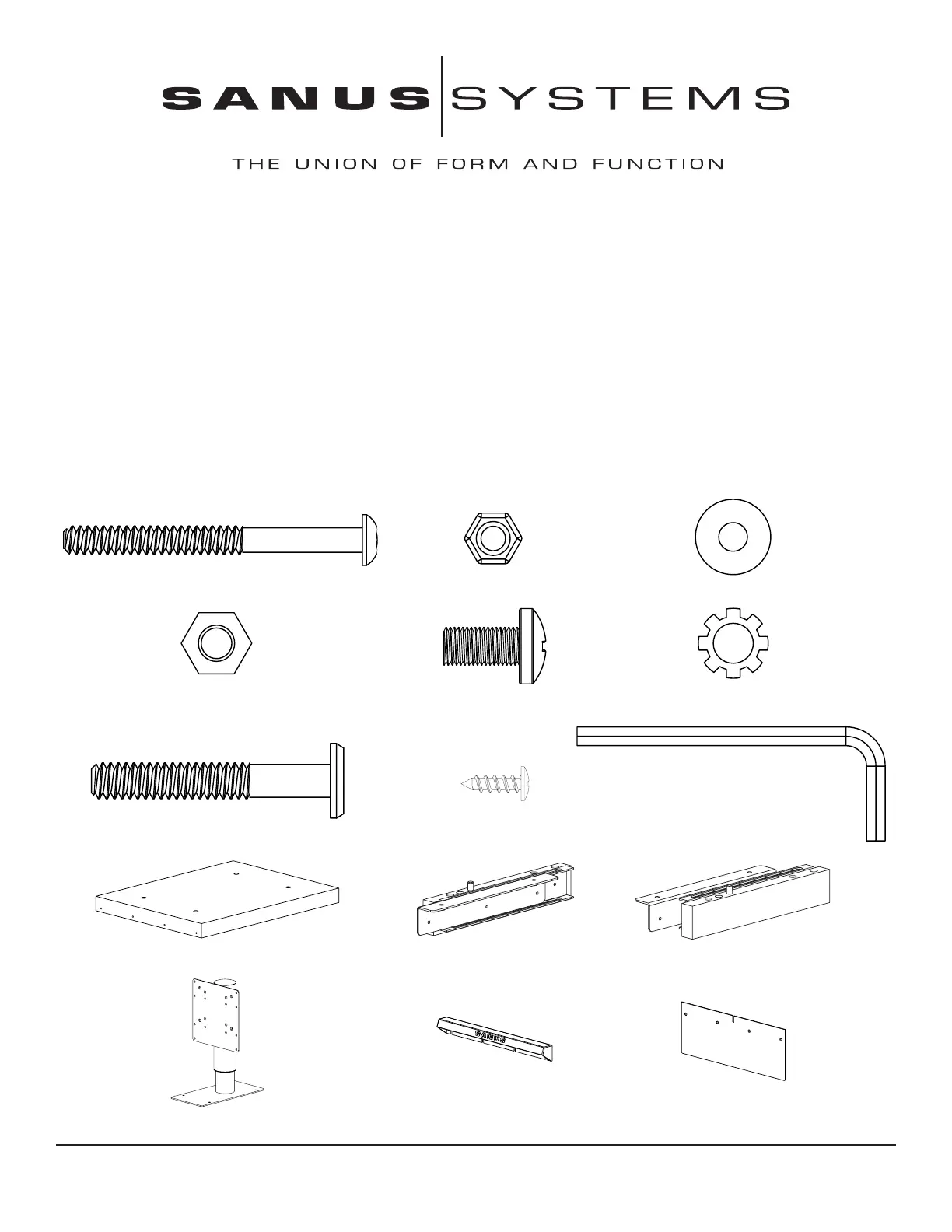
Check carefully to ensure that no hardware or parts are missing
Note: Hardware shown at actual size *Some items not shown at same scale
(6) Button Head Bolt - a (6) 1/4 20 Nut - b (6) Washer - c
(4) M8 Nut - d (4) M8 x 16 Bolt - e (4) M8 Lock Washer - f
(4) Furniture Bolt - g (4) Wood Screw - h (1) Allen Key - i
(1) Base - j (1) Left Glide - k (1) Right Glide - l
(1) Top Assembly - m * (1) Handle - n (1) Front Cover - o
Sanus Systems 2221 Hwy 36 West, Saint Paul, MN 55113 4.05.05
Customer Service: 800.359.5520. See complementary Sanus products at www.sanus.com
Product specificaties
| Merk: | Sanus |
| Categorie: | Flat panel steun |
| Model: | VMPO1 |
Heb je hulp nodig?
Als je hulp nodig hebt met Sanus VMPO1 stel dan hieronder een vraag en andere gebruikers zullen je antwoorden
Handleiding Flat panel steun Sanus

19 November 2025
18 November 2025
7 Oktober 2025
27 Maart 2025
17 November 2024
17 November 2024
5 September 2024
5 April 2024
5 April 2024
5 April 2024
Handleiding Flat panel steun
Nieuwste handleidingen voor Flat panel steun
20 Januari 2026
10 Januari 2026
7 Januari 2026
7 Januari 2026
6 Januari 2026
6 Januari 2026
6 Januari 2026
5 Januari 2026
5 Januari 2026
31 December 2026