SANDPIPER SludgeMaster SMA3-A Handleiding
Bekijk gratis de handleiding van SANDPIPER SludgeMaster SMA3-A (15 pagina’s), behorend tot de categorie Pomp. Deze gids werd als nuttig beoordeeld door 16 mensen en kreeg gemiddeld 5.0 sterren uit 8.5 reviews. Heb je een vraag over SANDPIPER SludgeMaster SMA3-A of wil je andere gebruikers van dit product iets vragen? Stel een vraag
Pagina 1/15
Warren Rupp, Inc. A Unit of IDEX Corporation P.O. Box 1568 Manseld, Ohio 44901-1568 USA (419) 524-8388 Fax (419) 522-7867 • www.warrenrupp.com
sma3dl1sm-REV1215 Model SMA3-A Page 1
SERVICE AND OPERATING MANUAL
Model SLUDGEMASTER
®
SMA3-A
Read these safety
warnings and
instructions in this
manual completely,
before installation and start-up of the pump.
It is the responsibility of the purchaser to
retain this manual for reference. Failure to
comply with the recommendations stated
in this manual will damage the pump, and
void factory warranty.
IMPORTANT
OPERATING INSTRUCTIONS
This pump has been tested prior to shipment from factory. The oil reservoir has
been partially lled at testing with air motor lubricant and should be completely lled
before operation. When reservoir is full, the pump will not require relling for approxi-
mately 50 hours of use. (See Lubrication Instructions.)
OPERATION
Your SludgeMaster is equipped with a mufer located at side of unit. Air exhaust
port is located at top of mufer and a ¾" NPT thread is provided to extend exhaust
port above liquid being pumped. Exhaust port must be extended above liquid to
prevent liquid and foreign material from entering air motor when not in opera-
tion. This can be done with a standard pipe, rigid plastic pipe, or hose as desired.
Connect air supply to air inlet tting and submerge into liquid to be pumped. Unit
requires 70 CFM maximum at 80 PSI (5.51 bar) air pressure. Operation at pressures
in excess of 120 PSI (8.27 bar) is not recommended.
When handling liquid with large stones or similar solid objects, it is desirable to
run unit at full speed. This provides greater inertia for handling heavy foreign objects
without stoppage due to lodging between impeller and pump casing.
Should a foreign object lodge and prevent pump from rotating, insert a rod or bar
through hole provided at bottom of strainer into impeller vanes and bump impeller
backwards (clockwise facing strainer end) until free. Strainer can be removed when
necessary; however, this normally will not be required.
LUBRICATION
The only regular servicing required is maintaining oil reservoir which is just
as important on this unit for proper lubrication as the oil supply is for an engine.
A one quart capacity oil reservoir is provided for bearing and shaft seal lubrication and
provides oil for automatic air motor lubricator. Five drops of oil per minute is automati-
cally dispensed into air stream for continuous air motor lubrication and to prevent rust
formation due to moisture which is present in any air supply. Check and rell reservoir
to oil ll plug level regularly with Shell TELLUS
®
T Oil 32 Premium Multigrade AW
Hydraulic Oil air motor lubricant, or an equivalent lightweight oil with rust inhibitor.
The automatic oiler will consume approximately 1 pint (473 cc) of oil in 50 hours of
operation. Oil reservoir should be completely drained and relled after approximately
100 hours operation to remove accumulated moisture.
It is benecial to pour a little oil into air inlet connection and run for a few minutes
before storing for long periods.
This unit is not harmed by running without liquid.
DISASSEMBLY
Remove upper row of six bolts and lift off air motor and upper housing assembly.
Filter element and lter housing are now exposed and can be removed. Lower half
of jaw type coupling is threaded on pump shaft and is removed by inserting drift pin
through hole in shaft to prevent rotation while turning coupling counterclockwise with
pipe wrench. DO NOT USE JAWS OF COUPLING TO LOOSEN AS THEY CAN BE
BROKEN.
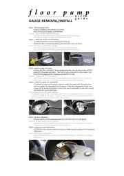
Remove spacer (item 25 on Repair Parts List) from shaft and remove governor
housing assembly by lifting with screwdriver from each side. This is done by inserting
screwdriver under male connectors (see Figure 1) and prying down on intermediate
housing. Intermediate housing can now be removed by removing lower row of six
bolts.
Figure 1
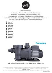
Figure 2
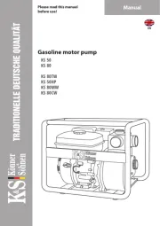
Airborne particles and
loud noise hazards.
Wear ear and eye
protection.
WARNING

Warren Rupp, Inc. A Unit of IDEX Corporation P.O. Box 1568 Manseld, Ohio 44901-1568 USA (419) 524-8388 Fax (419) 522-7867 • www.warrenrupp.com
Remove strainer assembly secured with four cap nuts. Impeller is removed by
inserting block of wood, hammer handle, or similar object between impeller vane and
pump casing (see Figure 2) to prevent rotation and turn shaft counterclockwise from
air motor end with drift pin inserted through hole in shaft. Remove shaft assembly
from volute casing by removing snap ring above oil seal, bump shaft and bearing from
casing. Rotating portion of shaft seal can now be removed from shaft and stationary
seal seat can be removed from casing.
REASSEMBLY
When installing shaft seal on shaft use a lightweight oil and locate seal at extreme
end of shaft so that carbon face of seal will contact seal seat before bearing enters
housing bore during assembly. This eliminates the possibility of carbon washer falling
out of position in seal cage while bumping shaft and bearing assembly into correct
position. Push oil seal and retainer into bore above bearing and install snap ring. Install
governor weights, spool and spring if removed. Lay o-ring into casing bore and install
intermediate housing. Install o-ring and drop governor housing into position and push
down into place. Slide sleeve and spacer onto shaft with spacer and shaft holes in
alignment. Install coupling and tighten securely with drift pin and pipe wrench with
same procedure as removal. (See Figure 3.) Insert o-ring into lter housing bore and
press lter element and housing into position as shown. (See Figure 4.) Install o-ring
into intermediate bore and o-ring on to counter bore at upper end of lter housing.
Assembly is now ready to receive air motor and housing assembly. If coupling half
on air motor shaft is removed, make certain coupling is relocated to correct posi-
tion as indicated dimensionally in Figure 5. Line up coupling jaws for engagement
by using bolt holes of castings as a reference. Rubber spider should be installed in
lower coupling half. Lower air motor and housing into place slowly to feel for correct
coupling engagement. When coupling is properly engaged, assembly can be pushed
down by hand. DO NOT FORCE ASSEMBLY TOGETHER WITH BOLTS. If air motor
assembly is lifted back up in attempting to engage blind coupling, make certain that
o-ring on top end of lter housing is still in position. If o-ring is out of position during
this blind assembly, air will by-pass the governor and over-speeding can occur. Fill
with recommended oil and run unit without pumping to check for possible oil leakage
at shaft seal or o-ring joints. Turn air supply on slowly to make certain that governor
is operating properly.
WARRANTY
This unit is guaranteed for a period of ve years against defective material and
workmanship.
PERMANENT INSTALLATIONS
NOTE: As mentioned, the SMA3-A pump does require that oil be in the reservoir
for bearing and motor lubrication. For permanent installations remove item 66, then
plug the hole with a
1
/
8
" pipe plug, part number 618-002-330. Fill the reservoir and
make sure that an in-line oiler (type oil as recommended) is used in the air supply to
the pump. Set lubricator at a usage rate of 1 pint (473 cc) every 50 hours. The motor
will then be lubricated by the in-line oiler and the bearing by the oil in the reservoir.
Figure 3
Figure 4
Figure 5
Figure 6
sma3dl1sm-REV1215 Model SMA3-A Page 2
Product specificaties
| Merk: | SANDPIPER |
| Categorie: | Pomp |
| Model: | SludgeMaster SMA3-A |
Heb je hulp nodig?
Als je hulp nodig hebt met SANDPIPER SludgeMaster SMA3-A stel dan hieronder een vraag en andere gebruikers zullen je antwoorden
Handleiding Pomp SANDPIPER

18 April 2024

18 April 2024
Handleiding Pomp
- Nibe
- Lifan
- Oase
- Enermax
- Eurom
- Grundfos
- Biltema
- Waldbeck
- Nowax
- Zodiac
- Bestway
- Heissner
- Bartscher
- Hecht
- Maruyama
Nieuwste handleidingen voor Pomp
15 September 2025

15 September 2025

15 September 2025

15 September 2025

15 September 2025

15 September 2025

7 September 2025
31 Augustus 2025

31 Augustus 2025
30 Augustus 2025