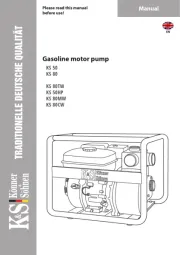
SANDPIPER PortaPump SPA 1-1/2-E Handleiding
Bekijk gratis de handleiding van SANDPIPER PortaPump SPA 1-1/2-E (5 pagina’s), behorend tot de categorie Pomp. Deze gids werd als nuttig beoordeeld door 47 mensen en kreeg gemiddeld 4.3 sterren uit 24 reviews. Heb je een vraag over SANDPIPER PortaPump SPA 1-1/2-E of wil je andere gebruikers van dit product iets vragen? Stel een vraag
Pagina 1/5

spa105dl3sm Model SPA1½-E and SPA40-E Design Level 3 Page 1
WARREN RUPP, INC., A unit of IDEX Corporation • 800 N. Main Street • Manseld, OH 44902 USA • (419) 524-8388 Fax (419) 522-7867
OPERATING INSTRUCTIONS
THE PUMP: This pump is a totally enclosed, submersible dewatering unit. It is
powered by a 1/3 HP, 12 volt DC 30 AMP motor. Battery clips on the power cord allow
easy connection to any 12 volt vehicle battery.
SWITCHING: The on-off switch is located on the power cord.
CONNECTING TO BATTERY: When connecting the clips to a battery, arcing is
eliminated by keeping the on-off switch in the “off” position. Connect the red battery
clamp to the positive (+) battery terminal. Connect the black battery clamp to ground:
preferably on the vehicle’s engine to a solid, metallic, stationary point. The connection
should be at least 18 inches (480mm) from the battery.
HOSE: Since the pump develops relatively low pressure, it is recommended that
non-collapsible hose be used for maximum pumping rates.
HOISTING & LOWERING: Attach a line to the metal handle on the top of the
pump for hoisting or lowering the unit. Do not use power cable for handling unit.
TO OPERATE: Lower unit into liquid to be pumped and activate switch. Pump
can be run for a few minutes without liquid, however, do not run completely dry for
extended periods. Damage to shaft seal may result.
RUNNING TIME: This unit draws about 30 amperes and can be operated
about 1hour on a fully charged 55 AMP-hour battery and still permit starting of
vehicle under normal conditions. Caution should be used when running time
exceeds 30 or 40 minutes without engine running to recharge battery, particularly
in cold weather when battery efciency is lowered. Battery size (AMP-hour rating)
and the use of other accessories such as lights and radios, etc., must be taken into
consideration for practical running periods without engine running.
OVERLOAD PROTECTION is provided by means of a 40 amp automatic reset
circuit breaker, located under top cover.
SERVICE AND OPERATING MANUAL
PortaPump
®
Model SPA 1½-E
Model SPA40-E
Design Level 3
Turn off before connecting
battery clamps to battery.
Arcing could result.
DANGER
IMPORTANT
Read these safety warnings
and instructions in this
manual completely, before
installation and start-up of the pump. It is
the responsibility of the purchaser to retain
this manual for reference. Failure to comply
with the recommendations stated in this
manual will damage the pump, and void
factory warranty.
DANGER
DANGER: Not for use with fluids
that have a flash point below 100°
F (38° C) [examples: gasoline, alcohol.]
Sparking could result in death.
Should unit not operate,
always check freeness
of rotation of impeller by inserting
screwdriver through hole in base
plate into slot in end of shaft.
IMPORTANT

Model SPA1½-E and SPA40-E Design Level 3 Page 2 spa105dl3sm
TROUBLE SHOOTING
NOTE: Most common cause of failure to run is due to hardened mud and sand at
impeller. Remove strainer to check.
MOTOR WILL NOT RUN:
1. Poor connection at battery.
2. Impeller locked with foreign material.
3. Insufcient impeller clearance.
4. Damaged power cable or loose connection internally in motor assembly.
5. Bad switch or circuit breaker. Connect power leads direct to motor leads to check.
6. Worn motor brushes or out of position to make contact with armature.
PERFORMANCE LOW:
1. Strainer screen partially plugged.
2. Impeller rubbing. Check freeness of rotation with screwdriver inserted through hole
in base plated into slotted end of shaft.
3. Battery not fully charged.
4. Discharge restriction such as kinked hose or excessive discharge head.
Motor runs backwards:
1. Check wiring for correct polarity.
SERVICE AND REPAIR INSTRUCTION
DISASSEMBLY: Impeller and shaft seal can be inspected and serviced
from lower end of pump by removal of 4 capscrews securing base plate, strainer
screen, and suction cover. Screwdriver slot is provided in end of motor shaft to turn
shaft while holding impeller for removal. This permits removal of impeller without
disassembly of upper motor housing to hold motor shaft. Alternately, there is a shaft
extension with two ats on the rear of the motor for use when the impeller is difcult to
remove. The upper motor cover must be removed to expose this shaft extension.
To service motor remove 4 hex nuts and bump top cover free from housing tube.
Raise sufciently to disconnect power cable connections. Slide housing tube up from
pump casing and motor will be exposed for service or removal.
When servicing the PortaPump and replacing the impeller (part number
444.001.010.) or suction cover (part number 258.001.157.) follow these instructions:The
impeller has been revised to typically require 1 shim (previously 7). The suction cover
has been revised to require 1 gasket (previously 5).
IMPORTANT: Make certain that wire leads are installed per diagram below.
Install top cover as indicated by arrow and instruction on top of cover. Make sure wires
do not contact motor shaft when installing motor cover.
WARRANTY
This unit is guaranteed for a period of 5 years against defective material
and workmanship.
Red Battery
Clamp
Switch
Aux Batt
Red
Motor
Black
Black Battery
Clamp
(Ground)
Circuit Breaker
510-003-000 Compression Lug
240-001-000 Twist Clamp
Product specificaties
| Merk: | SANDPIPER |
| Categorie: | Pomp |
| Model: | PortaPump SPA 1-1/2-E |
Heb je hulp nodig?
Als je hulp nodig hebt met SANDPIPER PortaPump SPA 1-1/2-E stel dan hieronder een vraag en andere gebruikers zullen je antwoorden
Handleiding Pomp SANDPIPER

18 April 2024

18 April 2024
Handleiding Pomp
- Coleman
- Aerotec
- Metabo
- B-Air
- Waldbeck
- Fieldmann
- Michelin
- Bestway
- OSIP
- Maruyama
- Bartscher
- Al-ko
- For_Q
- Ultimate Speed
- Worx
Nieuwste handleidingen voor Pomp
15 September 2025

15 September 2025

15 September 2025

15 September 2025

15 September 2025

15 September 2025

7 September 2025
31 Augustus 2025
31 Augustus 2025
30 Augustus 2025