Ruckus Wireless ZoneFlex T710 Handleiding
Ruckus Wireless Access point ZoneFlex T710
Bekijk gratis de handleiding van Ruckus Wireless ZoneFlex T710 (50 pagina’s), behorend tot de categorie Access point. Deze gids werd als nuttig beoordeeld door 96 mensen en kreeg gemiddeld 4.2 sterren uit 4 reviews. Heb je een vraag over Ruckus Wireless ZoneFlex T710 of wil je andere gebruikers van dit product iets vragen? Stel een vraag
Pagina 1/50
Copyright © 2016 Ruckus Wireless, Inc.
Published August 2016, Part Number 800-70938-001 Rev E
Page 1 of 4
T710 Access Point
Quick Setup Guide
This Mounting Guide provides step-by-step instructions on how to
field-install the Ruckus Wireless T710 access point (AP).
For detailed information on planning the installation, performing a site
survey, and operating the T710, refer to the ZoneFlex Outdoor Access
Point User Guide, available at https://support.ruckuswireless.com
.
WARNING:Only trained and qualified personnel should be allowed to
install, replace, or service this equipment.
WARNING: Installation of this equipment must comply with local and
national electrical codes.
CAUTION:Make sure that you form a 80mm - 130mm (3”-5”) drip
loop in any cable that is attached to the AP or the building. This will
prevent water from running along the cable and entering the AP or the
building where the cable terminates.
CAUTION:Be sure that grounding is available and that it meets local
and national electrical codes. For additional lightning protection, use
lightning rods and lightning arrestors.
CAUTION:Make sure that proper lightning surge protection
precautions are taken according to local electrical code.
WARNING:Ruckus Wireless strongly recommends that you wear eye
protection before mounting the T710.
THIS GUIDE IN OTHER LANGUAGES
请从以下网站获得该指南的简体中文版
https://support.ruckuswireless.com
.
Vous trouverez la version française de ce guide à l'adresse suivante
https://support.ruckuswireless.com
.
このガイドの⽇本語版は https://support.ruckuswireless.com
でご覧ください。
이가이드의한국어버전은웹사이트
(https://support.ruckuswireless.com
)에서 확인하시기 바랍니다.
Veja a versão em português (Brasil) deste guia em
https://support.ruckuswireless.com.
Puede ver la versión en español (América Latina) de esta guía en
https://support.ruckuswireless.com.
BEFORE YOU BEGIN
Before deploying your Ruckus Wireless T710, verify that all items listed
in Package Contents
are included in the package. If any item is
damaged or missing, notify your authorized Ruckus Wireless sales
representative. Also, make sure that you have the required hardware
and tools.
REQUIRED HARDWAREAND TOOLS
•Customer-supplied outdoor-rated three-wire (1-2mm
2
or 14-
18AWG) AC cable
•1/2” (13mm) flat-blade screwdriver or equivalent
•No. 2 Phillips screwdriver
•Small flat-blade screwdriver
•Torque wrench or torque screwdriver with sockets
•Long-nose pliers
•Electrical wire stripping and terminal crimping pliers
•Pipe or pole --OR-- a sturdy flat surface
•Electric drill with drill bits and customer-supplied wall anchors, flat
washers, and hex nuts for flat-surface mount
•Four factory-supplied 1/2” (12.7mm) wide stainless steel
adjustable clamps, 2.5” (63.5mm) diameter, for main mounting
bracket on smaller poles
•Ruler
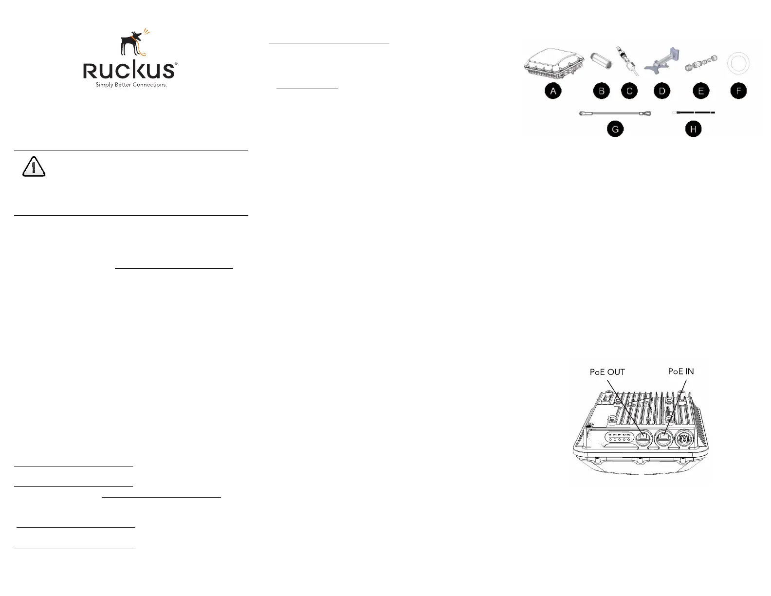
PACKAGE CONTENTS
A complete T710 field installation package includes all of the items
listed below (see Figure 1for illustrations):
•T710 Access Point (A)
•M25 data cable gland extender (B)
•Three M25 data cable glands (C)
•Outdoor AP Mounting Bracket (D), consists of:
•Mounting bracket
•U-joint bracket
•Linkage bracket
•AP bracket
•AC Power Cable End Connector (E)
•Cable Gland Extender Flat Gasket (F)
•Safety cable kit (G)
•One ground wire with lug (H)
•Service Level Agreement/Limited Warranty Statement
•Regulatory Statement
•Ruckus Wireless AP Getting Started Guide
•Declaration of Conformity
•This Quick Setup Guide
Figure 1:Package Contents
STEP 1: CONNECTING AND SEALING THE RJ-45
C
ABLES
The T710 may use zero, or one or two RJ-45 cables, one for Ethernet
when configured as a Root AP (RAP), and another when the T710 is
supplying PoE out to a peripheral device, such as a small cell or micro
cell radio. When the T710 uses RJ-45 cables, connect and seal the
cables using the M25 data cable glands as shown in Figure 3.
WARNING:Do not use any PoE injector not tested and approved by
Ruckus Wireless to power the T710 Access Point.
WARNING: Do not plug PoE IN power into the PoE OUT port. See
Figure 2.
WARNING: If using PoE OUT, it is MANDATORY to use the custom
Ruckus supplied 60W PoE injector (part #902-0180-XX00), or to use
AC power.
WARNING: If using a PoE switch to supply power to the T710, 30W
MUST be reserved for the T710 on the switch. Failure to ensure a
30W supply may result in unpredictable operation of the access point.
Additionally, if using a PoE switch, the T710’s PoE OUT port cannot be
used to power additional devices.
Figure 2:PoE IN and PoE OUT ports
1Feed the end of the cable through the sealing nut, rubber O-ring,
clamping ring assembly and cable gland base as shown in Figure
3.
CAUTION!The minimum software revision for the T710
is ZoneFlex (ZF) 9.13 or later, or SmartZone (SZ) 3.4 or
later.
DO NOT CONNECT THE T710 TO A RUCKUS
WIRELESS ZONEDIRECTOR RUNNING 9.12.2 OR
EARLIER.
Product specificaties
| Merk: | Ruckus Wireless |
| Categorie: | Access point |
| Model: | ZoneFlex T710 |
| Kleur van het product: | Wit |
| Gewicht: | 2950 g |
| Breedte: | 241 mm |
| Diepte: | 317 mm |
| Hoogte: | 95 mm |
| Internationale veiligheidscode (IP): | IP67 |
| LED-indicatoren: | Ja |
| Plaatsing: | Ceiling, Table, Wall |
| Frequentieband: | 5 GHz |
| Aantal Ethernet LAN (RJ-45)-poorten: | 2 |
| Bevestigingsmogelijkheid voor kabelslot: | Ja |
| Kabelslot sleuf type: | Kensington |
| Vermogensverbruik (max): | 25 W |
| MIMO: | Ja |
| Modulatie: | DPSK |
| Ethernet LAN, data-overdrachtsnelheden: | 10,100,1000 Mbit/s |
| Netwerkstandaard: | IEEE 802.11a, IEEE 802.11ac, IEEE 802.11b, IEEE 802.11g, IEEE 802.11n |
| Ondersteunde beveiligingsalgoritmen: | WPA-PSK, WPA-TKIP, WPA2-AES |
| Soort antenne: | Intern |
| Antennas quantity: | 4 |
| Antenne versterkingsniveau (max): | 8 dBi |
| Aantal gebruikers: | 512 gebruiker(s) |
| Intern: | Ja |
| Draadloos LAN data-overdrachtsnelheid (max): | 1733 Mbit/s |
| Web-gebaseerd management: | Ja |
| MIMO-type: | Multi User MIMO |
| Maximale overdrachtssnelheid van gegevens: | 1733 Mbit/s |
| 2,4 GHz: | Ja |
| 5 GHz: | Ja |
| Kanaalbandbreedte: | 80 MHz |
| Quality of Service (QoS): | Ja |
| Fit AP-modusfuncties: | Hotspot 2.0 |
| Adaptieve bandbreedtebeheer: | Ja |
| Service Set Identifier (SSID) functies: | Hidden SSID |
| IPv4- & IPv6-functies: | IPv4/IPv6 access-control list (ACL) |
| Power over Ethernet (PoE): | Ja |
| Antennefuncties: | Ingebouwde antenne |
| Aantal kanalen: | 3 kanalen |
| Bandbreedte: | 5 GHz |
| Max WLAN Connections: | 512 |
| Draadloze indringerdetectiesysteem (WIDS): | Ja |
| Bedrijfstemperatuur (T-T): | -40 - 65 °C |
| Relatieve vochtigheid in bedrijf (V-V): | 0 - 95 procent |
| Aantal SSID-ondersteuningen: | 31 |
Heb je hulp nodig?
Als je hulp nodig hebt met Ruckus Wireless ZoneFlex T710 stel dan hieronder een vraag en andere gebruikers zullen je antwoorden
Handleiding Access point Ruckus Wireless

20 December 2023
20 December 2023
20 December 2023
20 December 2023
20 December 2023
20 December 2023
20 December 2023
20 December 2023
20 December 2023
20 December 2023
Handleiding Access point
Nieuwste handleidingen voor Access point
8 Juli 2026
22 Juni 2026
19 Juni 2026
15 Juni 2026
14 Juni 2026
14 Juni 2026
14 Juni 2026
14 Juni 2026
14 Juni 2026
14 Juni 2026