Ruckus Wireless ZoneFlex T610 Handleiding
Ruckus Wireless Access point ZoneFlex T610
Bekijk gratis de handleiding van Ruckus Wireless ZoneFlex T610 (4 pagina’s), behorend tot de categorie Access point. Deze gids werd als nuttig beoordeeld door 45 mensen en kreeg gemiddeld 4.4 sterren uit 7 reviews. Heb je een vraag over Ruckus Wireless ZoneFlex T610 of wil je andere gebruikers van dit product iets vragen? Stel een vraag
Pagina 1/4
Copyright © 2016 Ruckus Wireless, Inc.
Published June 2016, Part Number 800-71230-001 Rev A
Page 1 of 4
T610 Access Point
Quick Setup Guide
This Quick Setup Guide provides step-by-step instructions on how to
field-install the Ruckus Wireless T610 access point (AP).
For detailed information on planning the installation, performing a site
survey, and operating the T610, refer to the ZoneFlex Outdoor Access
Point User Guide, available at https://support.ruckuswireless.com
.
WARNING:Only trained and qualified personnel should be allowed to
install, replace, or service this equipment.
WARNING: Installation of this equipment must comply with local and
national electrical codes.
CAUTION:Make sure that you form a 80mm - 130mm (3”-5”) drip
loop in any cable that is attached to the AP or the building. This will
prevent water from running along the cable and entering the AP or the
building where the cable terminates.
CAUTION:Be sure that grounding is available and that it meets local
and national electrical codes. For additional lightning protection, use
lightning rods and lightning arrestors.
CAUTION:Make sure that proper lightning surge protection
precautions are taken according to local electrical code.
WARNING:Ruckus Wireless strongly recommends that you wear eye
protection before mounting the T610.
THIS GUIDE IN OTHER LANGUAGES
请从以下网站获得该指南的简体中文版
https://support.ruckuswireless.com
.
Vous trouverez la version française de ce guide à l'adresse suivante
https://support.ruckuswireless.com
.
このガイドの⽇本語版は https://support.ruckuswireless.com
でご覧ください。
이가이드의한국어버전은웹사이트
(https://support.ruckuswireless.com)에서 확인하시기 바랍니다.
Veja a versão em português (Brasil) deste guia em
https://support.ruckuswireless.com.
Puede ver la versión en español (América Latina) de esta guía en
https://support.ruckuswireless.com.
BEFORE YOU BEGIN
Before deploying your Ruckus Wireless T610, verify that all items listed
in Package Contents
are included in the package. If any item is
damaged or missing, notify your authorized Ruckus Wireless sales
representative. Also, make sure that you have the required hardware
and tools.
REQUIRED HARDWAREAND TOOLS
•Customer-supplied outdoor-rated three-wire (1-2mm
2
or 14-
18AWG) AC cable
•1/2” (13mm) flat-blade screwdriver or equivalent
•No. 2 Phillips screwdriver
•Small flat-blade screwdriver
•Torque wrench or torque screwdriver with sockets
•Long-nose pliers
•Electrical wire stripping and terminal crimping pliers
•Pipe or pole --OR-- a sturdy flat surface
•Electric drill with drill bits and customer-supplied wall anchors, flat
washers, and hex nuts for flat-surface mount
•Four factory-supplied 1/2” (12.7mm) wide stainless steel
adjustable clamps, 2.5” (63.5mm) diameter, for main mounting
bracket on smaller poles
•Ruler
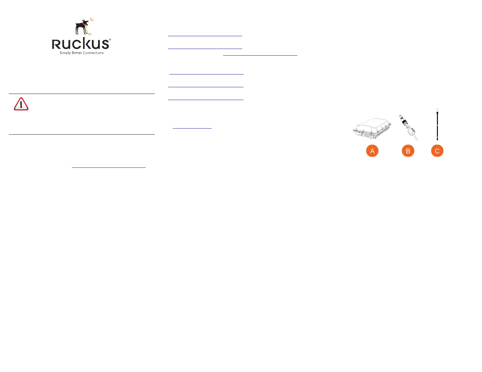
PACKAGE CONTENTS
A complete T610 field installation package includes all of the items
listed below (see Figure 1for illustrations):
•T610 Access Point (A)
•Two M25 data cable glands (B)
•Ground wire with lug (C)
•Service Level Agreement/Limited Warranty Statement
•Declaration of Conformity
•Regulatory Statement
•Ruckus Wireless AP Getting Started Guide
•This Quick Setup Guide
Figure 1:Package Contents
NOTE:The outdoor AP Mounting Bracket and security cable are
optional accessories that must be purchased separately.
CAUTION!The minimum software revision for the T610
is ZoneDirector (ZD) 9.13.1 or later, or SmartZone (SZ) 3.4
or later, or standalone AP firmware 104.0 or later.
DO NOT CONNECT THE T610 TO A RUCKUS
WIRELESS ZONEDIRECTOR RUNNING 9.13 OR
EARLIER.
Product specificaties
| Merk: | Ruckus Wireless |
| Categorie: | Access point |
| Model: | ZoneFlex T610 |
Heb je hulp nodig?
Als je hulp nodig hebt met Ruckus Wireless ZoneFlex T610 stel dan hieronder een vraag en andere gebruikers zullen je antwoorden
Handleiding Access point Ruckus Wireless

20 December 2023
20 December 2023
20 December 2023
20 December 2023
20 December 2023
20 December 2023
20 December 2023
20 December 2023
20 December 2023
20 December 2023
Handleiding Access point
Nieuwste handleidingen voor Access point
8 Juli 2026
22 Juni 2026
19 Juni 2026
15 Juni 2026
14 Juni 2026
14 Juni 2026
14 Juni 2026
14 Juni 2026
14 Juni 2026
14 Juni 2026