RDL RU-VCA6A Handleiding
Bekijk gratis de handleiding van RDL RU-VCA6A (2 pagina’s), behorend tot de categorie Processor. Deze gids werd als nuttig beoordeeld door 39 mensen en kreeg gemiddeld 4.8 sterren uit 8 reviews. Heb je een vraag over RDL RU-VCA6A of wil je andere gebruikers van dit product iets vragen? Stel een vraag
Pagina 1/2
RACK-UP
®
SERIES
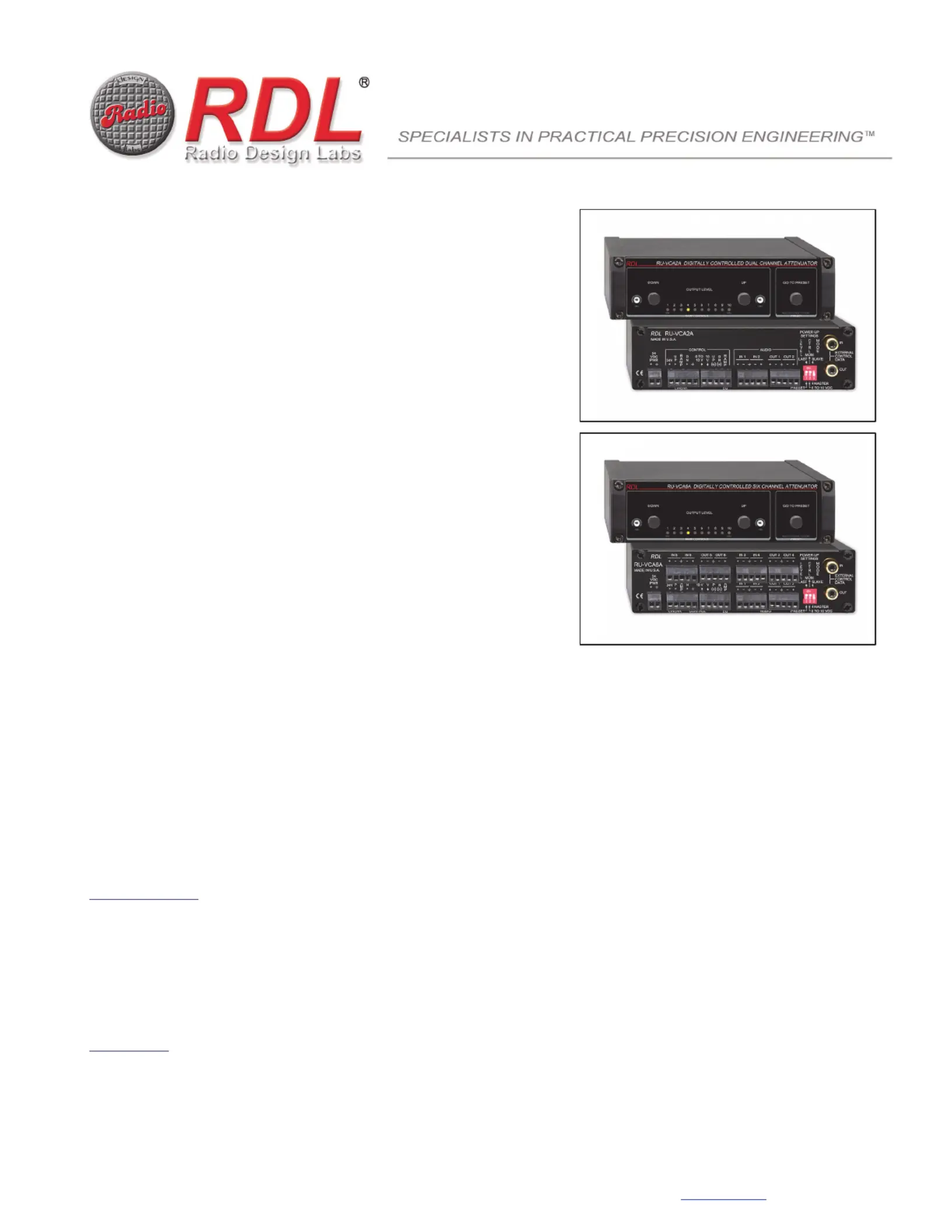
Models RU-VCA2A & RU-VCA6A
Digitally Controlled Attenuators
Local or Remote Audio Level Control
Mono or Stereo Attenuation (RU-VCA2A)
Six Channel / Surround Attenuation (RU-VCA6A)
Noiseless Zero-Crossing Adjustment Steps
96 dB Attenuation Range in 0.5 dB Steps
Data Bus Provides Adjustment of Multiple Modules
Multiple Remote Control Locations Possible
Precise Level Tracking on Each Channel
Balanced or Unbalanced Line Inputs/Outputs
Adjustable Ramp Up/Down Rates
Controllable Using Various RDL Remote Controls
Selectable Level Control Options:
Pushbuttons (Internal or External)
Momentary Pulses (External/Rotary Encoder)
0 to10 Vdc or 10 k Potentiometer
Selectable Power-Up Return to PRESET or LAST Level
Selectable MASTER/SLAVE Mode for Control Expansion
The RU-VCA is part of the group of RACK-UP products from Radio Design Labs. RACK-UPs feature the advanced circuitry for which RDL products are known,
combined with accessible user-friendly controls and displays. The ultra compact design permits high-density installations, with three products mounted in a single rack
unit. Optional brackets permit mounting a RACK-UP module above, below, or in front of any flat surface!
APPLICATION: The RU-VCA2A is a full-featured studio-quality dual-channel audio attenuator module for local and/or remote control of
balanced or unbalanced line-level sources. The RU-VCA6A has all the features of an RU-VCA2A with four additional audio channels for
level control of surround sound (5.1) or six individual analog audio channels. Each module can be remote controlled from a single or
multiple locations. Rear-panel terminals provide flexible control options using a variety of RDL remote controls or OEM equipment.
Audio levels are controlled in 0.5 dB steps using noiseless zero-crossing digital attenuators for optimum reliability, precise tracking and
long-term click-free service. Exceptional wide-band low-noise performance makes the RU-VCA2A and RU-VCA6A suited to level
adjustment in the most demanding applications. Rear-panel inputs and outputs may each be wired balanced or unbalanced.
The RU-VCA2A and RU-VCA6A power up in one of two operating modes set by a rear-panel switch.
MOM (momentary) Mode
In the MOM (momentary) mode, audio level is controlled by momentary pushbuttons or pulses. Remote terminals and front-panel
pushbuttons are provided for up and down ramping control. If either button is held in, the audio will ramp automatically. If a button is
pulsed (< 0.5 second), the audio will increment one step. The time of both the UP and DOWN ramps is individually adjustable on the front
panel. Pushing remote UP and DOWN buttons simultaneously, or pressing the front-panel GO TO PRESET button, returns the audio to a
preset level. The preset level is stored by adjusting the desired level using the UP and DOWN buttons, then pressing and holding the
front-panel PRESET button for 3 seconds. A rear-panel switch sets the audio power-up level to either the preset level or the last level
setting used. Multiple remote control locations are possible in the mode. External control pulses may MOMbe either of positive polarity or
pulled-to-ground (open-collector).
0 to 10 VDC Mode
In the 0 to 10 VDC mode the preset function is disabled and the audio level is controlled by a remote 10 k linear taper pot or by 0 to 10
Vdc. A single remote control location is possible using a remote 10 k pot.
In both operating modes, two separate 0 to 10 Vdc outputs are provided. The linear RAMP output drives the level display on RDL remote
controls; the EQRAMPoutput is used to control an automatic RDL Loudness Equalizer (see ST-LEQ1). A front-panel 10-LED string
display indicates the relative audio level. Control expansion is possible using the EXTERNAL CONTROL DATAjacks. One module can
be set as a MASTER module to control the level of one or more additional RU-VCA2A or RU-VCA6A modules set to the SLAVE mode.
RDL
659 6
th
St.
Prescott, AZ., USA 86301
(928) 443-9391
FAX (928) 443-9392
www.rdlnet.com
max
Product specificaties
| Merk: | RDL |
| Categorie: | Processor |
| Model: | RU-VCA6A |
Heb je hulp nodig?
Als je hulp nodig hebt met RDL RU-VCA6A stel dan hieronder een vraag en andere gebruikers zullen je antwoorden
Handleiding Processor RDL

2 April 2025
Handleiding Processor
Nieuwste handleidingen voor Processor
28 April 2026
27 April 2026
27 Januari 2026
27 Januari 2026
1 December 2025
24 November 2025
21 November 2025
4 November 2025
4 November 2025
4 November 2025