Philips SQM7842 Handleiding
Philips
Niet gecategoriseerd
SQM7842
Bekijk gratis de handleiding van Philips SQM7842 (2 pagina’s), behorend tot de categorie Niet gecategoriseerd. Deze gids werd als nuttig beoordeeld door 242 mensen en kreeg gemiddeld 4.5 sterren uit 121.5 reviews. Heb je een vraag over Philips SQM7842 of wil je andere gebruikers van dit product iets vragen? Stel een vraag
Pagina 1/2

Engli s h
1 Important safety instructions
Caution
• Read these instructions before you begin. If you are unsure of any
part of the process, contact a professional contractor or installer
for assistance. Improper installation can result in injury or damage.
• The wall or mounting surface must be capable of supporting
the combined weight of the mount and the display; if not, the
structure must be reinforced.
• Locate pipes, wires, or any other hazards in the wall where you
wish to install the mount before drilling.
• Safety gear and proper tools must be used. Failure to do so can
result in injury or damage.
• Two people are recommended for installation. Do not attempt to
lift a heavy display without assistance.
• Follow all instructions and recommendations regarding adequate
ventilation and suitable locations for mounting your display.
Consult the owner‘s manual for your particular display for more
information.
• This wall mount is intended for use only with the maximum
weight of 45 kg (100 lbs). Use with heavier than the maximum
weights indicated may result in instability causing possible injury.
2 Tilt wall mount (for LCD, Plasma, and LED displays)
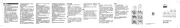
What's in the box
Wall plate (x1)
Mount arm (x2)
User manual (x1)
Hardware kit (x1)
Hardward kit
A
M8 x 63 lag bolt (x4)
B
Lag bolt washer (x4)
C
Concrete anchor (x4)
D
M6 x 12 screw (x4)
E
M6 x 30 screw (x4)
F
M8 x 12 screw (x4)
G
M8 x 30 screw (x4)
H
M6 washer (x4)
I
M8 washer (x4)
J
Spacer (x8)
Tools required
• Phillips head screw driver
• Ratchet or driver with 13 mm (1/2”) socket
• Electric or portable drill
• 6 mm (1/4”) drill bit and stud nder for drywall installation
• 10 mm (3/8”) Masonry bit for concrete installation
3 Installation
Mount to the drywall
Caution
For safety reasons, this mount must be secured to at least two
wood studs no less than 16” apart. The studs must be capable of
supporting the combined weight of the mount and display.
1 Use a high quality stud nder to locate two adjacent
studs where you wish to install your mount. Mark both
edges of each stud to help identify the exact center.
Note
You must use the center of each stud to avoid cracking or splitting
the wood during installation.
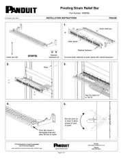
2 Place the wall plate against the wall and level it using the
integrated bubble level.
3 While another person holds the wall plate in position,
mark four locations (two per stud) for securing the
mount to the wall (see Fig. 1).
4 Set the wall plate aside and drill a 6 mm (1/4”) pilot hole
at each marked location.
5 Place the wall plate back against the wall and attach it
using the lag bolts
A
and lag bolt washers
B
provided
(see Fig. 2). Do not over-tighten these bolts and do not
release the wall plate until all bolts are in place. Ensure
that the wall plate remains level after all bolts are secured.
Mount to the concrete wall
Caution
For safety reasons, the concrete wall must be capable of
supporting the combined weight of the mount and the display. The
manufacturer takes no responsibility for failure caused by walls of
insufcient strength.
1 Place the wall plate against the wall in the desired
location and level it using the integrated bubble level.
2 While another person holds the wall plate in place, mark
four evenly spaced locations on the wall for securing the
mount (see Fig. 3).
3 Set the wall plate aside and drill a 10 mm (3/8”) hole at
each marked location. Remove any excess dust from the
holes.
4 Insert a concrete anchor
C
into each hole so that it is
ush with the concrete surface (see Fig. 4). A hammer can
be used to lightly tap the anchors into place if necessary.
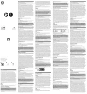
A
B
C
D
E
F
G
H
I
J
**
1 2
3
4
5
6
7
8 9
2015 © Gibson Innovations Limited.
All rights reserved.
This product has been manufactured by, and is sold
under the responsibility of Gibson Innovations Ltd., and
Gibson Innovations Ltd. is the warrantor in relation to
this product.
Philips and the Philips Shield Emblem are registered
trademarks of Koninklijke Philips N.V. and are used
under license from Koninklijke Philips N.V.
UM_SQM7842
27_EN_V1.0
WK15314
SQM7842
Register your product and get support at
www.philips.com/support
User manual
Manual del usuario
sqm7842_27_2L_um_150730.indd 1-3 30/07/2015 18:00:58

Note
If the concrete wall is covered by a layer of plaster or drywall, the
concrete anchor must pass completely through the layer to rest
ush with the concrete surface.
5 Place the wall plate back against the wall and attach it
using the lag bolts
A
and lag bolt washers
B
provided
(see Fig. 2). Do not over-tighten these bolts and do not
release the wall plate until all bolts are in place. Ensure
that the wall plate remains level after all bolts are secured.
Attaching the mount arms to the display
Caution
Use extra care during this part of the installation. If possible,
avoid facing down your display as it may damage the viewing
surface.
Note
This mount comes with a selection of different screw diameters
and lengths to accommodate a wide variety of display models. Not
all of the hardware in the kit will be used. If you cannot nd the
appropriate screw size in the kit provided, consult the manufacturer
of your display for more information.
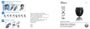
1 Determine the correct length of screw to use by
examining the back of your display:
• If the back of your display is at and the mounting holes
are ush with the surface, you will use the shorter
screws (
D
or
F
) from the hardware kit.
• If the back of your display is curved, has a protrusion, or
if the mounting holes are recessed, you will need to use
the longer screws (
E
or
G
) and may also need to use
the spacers
J
.
2 Determine the correct diameter of screw to use
carefully by trying different size (M6 and M8) from the
hardware kit. Do not force any of the screws – if you
feel resistance, stop immediately and try a smaller
diameter screw.
3 Attach the mount arms to the back of your display using
the screws identied in steps 1 and 2:
• If you are using M6 screws you will need to use M6
washers
H
. If you are using M8 screws you will need to
use M8 washers
I
(see Fig. 5).
• If you are using the longer screws on a display with a
curved or recessed back, you may also need to use
spacers
J
. Use one spacer or two spacers stacked as
needed. (see Fig. 6).Only use a spacer if necessary
Note
The mount arms must be attached with the tilt knobs (*) facing
outward (i.e. away from the middle of the display) (see Fig. 7).
Otherwise, the tilt function cannot be accessed.
Final assembly
1 With the help of another person, carefully lift your display
and place it on the wall plate. Do not release the display
until the mount arms have securely hooked onto the
wall plate.
2 Tighten the safety screw located on each mount arm
using the Phillips head screw driver (see Fig. 8) to prevent
the display from being lifted from the wall plate.
Caution
The safety screws must be tightened at all times to prevent the
display from being accidentally knocked from the mount.
4 Operation and adjustment
• To change the tilt angle of your display, have one person
holding the display rmly in place while another person
loosening the tilt knobs located on each mount arm.
Once loosened, you may move your display to the
desired position. Re-tighten the tilt knobs to lock the tilt
angle in place. Do not release the display until both tilt
knobs are fully tightened. If you are unable loosen or fully
tighten the knob by hand, the Phillips head screw driver
can also be used (see Fig. 9).
• Periodically clean your mount with a dry cloth. Inspect all
screws and hardware at regular intervals to ensure that
no connections have become loose over time. Re-tighten
as needed.
5 Specifications
Display Size 37” to 65”
Maximum Load 45 kg (100 lbs)
Mounting Pattern
max. 800 mm x 400 mm (31.4” x 15.7”)
Tilt Range up to 15° (tilting down)
Prole 4.4 cm (1.7”)
Español
1 Instrucciones de seguridad importantes
Precaución
• Lea estas instrucciones antes de comenzar. Si no está seguro de
algún paso del proceso, póngase en contacto con un contratista
o instalador profesional para obtener ayuda. Una instalación
incorrecta puede producir lesiones o daños.
• La pared o la supercie de montaje deben ser capaces de
aguantar el peso combinado del soporte de montaje y de la
pantalla. Si no es así, la estructura se debe reforzar.
• Localice las tuberías, cables y otros peligros en la pared en la que
desea instalar el soporte antes de comenzar a perforar.
• Debe utilizar un engranaje de seguridad y herramientas adecuadas.
Si no lo hace, se pueden producir lesiones o daños.
• Se recomienda que la instalación la realicen dos personas. No
intente levantar una pantalla pesada sin ayuda.
• Siga todas las instrucciones y recomendaciones relativas a la
ventilación correcta y a las ubicaciones apropiadas para el montaje
de la pantalla. Consulte el manual de instrucciones del modelo de
su pantalla para obtener más información.
• Este soporte de montaje en pared se ha diseñado para su
uso con un peso máximo de 45 kg. El hecho de utilizarlo con
productos de mayor peso que el indicado puede dar lugar a
inestabilidad y producir lesiones.
2 Montaje en pared inclinado (para pantallas
LCD, LED y de plasma)
Contenido de la caja
Placa de pared (1)
Brazo de montaje (2)
Manual de usuario (1)
Kit de tornillería (1)
Kit de tornillería
A
Tirafondos M8 x 63 (4)
B
Arandela para tirafondos (4)
C
Taco para hormigón (4)
D
Tornillos M6 x 12 (4)
E
Tornillos M6 x 30 (4)
F
Tornillos M8 x 12 (4)
G
Tornillos M8 x 30 (4)
H
Arandela M6 (4)
I
Arandela M8 (4)
J
Espaciadores (8)
Herramientas necesarias
• Destornillador plano Phillips
• Llave de trinquete o atornillador con boca de 13 mm
• Taladro eléctrico o portátil
• Broca de 6 mm y detector de montantes para instalación en
tabiques de yeso
• Broca para hormigón de 10 mm para instalación en hormigón
3 Instalación
Montaje en tabiques de yeso
Precaución
Por motivos de seguridad, este soporte se debe jar al menos a dos montantes
de madera que no estén separados más de 40 cm. Los montantes deben poder
soportar el peso combinado del soporte y la pantalla.
1 Utilice un detector de montantes de buena calidad para
encontrar dos montantes adyacentes en el lugar en el que
desea instalar el soporte. Marque los dos bordes de cada
montante para identicar el centro exacto.
Nota
Debe utilizar el centro de cada montante para evitar que la madera
se agriete o se parta durante la instalación.
2 Coloque la placa de pared contra la pared y nivélela
utilizando el nivel de burbuja suministrado.
3 Mientras otra persona sujeta la placa de pared en su lugar,
marque las cuatro ubicaciones (dos por montante) para
jar el soporte a la pared (consulte la imagen 1).
4 Retire la placa de pared y perfore un oricio guía de
6 mm en cada ubicación marcada.
5 Coloque la placa de pared de nuevo contra la pared
y fíjela mediante los tirafondos
A
y las arandelas para
tirafondos
B
que se incluyen (consulte la imagen 2). No
apriete los tirafondos en exceso y no suelte la placa de
pared hasta que todos los tirafondos estén en su lugar.
Asegúrese de que la placa de pared permanezca nivelada
después de apretar todos los tirafondos.
Montaje en paredes de hormigón
Precaución
Por motivos de seguridad, la pared de hormigón debe poder
soportar el peso combinado del soporte y la pantalla. El fabricante
no asume responsabilidad alguna por las averías provocadas por una
resistencia insuciente de la pared.
1 Coloque la placa de pared contra la pared en la ubicación que
desee y nivélela utilizando el nivel de burbuja suministrado.
2 Mientras otra persona sujeta la placa de pared en su lugar,
marque cuatro ubicaciones distribuidas uniformemente
en la pared para jar el soporte (consulte la imagen 3).
3 Retire la placa de pared y perfore un oricio de 10 mm en cada
ubicación marcada. Elimine el exceso de polvo de los oricios.
4 Introduzca un taco para hormigón
C
en cada oricio hasta
que estén a ras de la supercie de hormigón (consulte la
imagen 4). Si es necesario, puede utilizar un martillo para
golpear los tacos suavemente hasta que estén en su lugar.
Nota
Si la pared de hormigón está cubierta por una capa de masilla o
yeso, el taco para hormigón debe atravesar completamente la capa
hasta que esté a ras de la supercie de hormigón.
5 Coloque la placa de pared de nuevo contra la pared y fíjela
mediante los tirafondos
A
y las arandelas para tirafondos
B
que se incluyen (consulte la imagen 2). No apriete los tirafondos
en exceso y no suelte la placa de pared hasta que todos los
tirafondos estén en su lugar. Asegúrese de que la placa de pared
permanezca nivelada después de apretar todos los tirafondos.
Fijación de los brazos de montaje a la pantalla
Precaución
Tenga especial cuidado durante esta parte de la instalación. Si es posible, evite
colocar la pantalla bocabajo, p2-ya que podría dañar la supercie de visualización.
Nota
Este soporte incluye una selección de tornillos de diferentes diámetros y
longitudes para adaptarse a una amplia variedad de modelos de pantalla.
No será necesario utilizar toda la tornillería incluida en el kit. Si no
encuentra el tornillo del tamaño adecuado en el kit incluido, consulte al
fabricante de su pantalla para obtener más información.
1 Determine la longitud correcta del tornillo que va a
utilizar examinando la parte posterior de la pantalla:
• Si la parte posterior de la pantalla es plana y los oricios
de montaje están a ras de la supercie, utilice los tornillos
más cortos (
D
o
F
) del kit de tornillería.
• Si la parte posterior de la pantalla es curva, tiene un saliente
o los oricios de montaje están hundidos, deberá utilizar los
tornillos más largos (
E
o
G
) del kit de tornillería.
2 Determine el diámetro correcto del tornillo que va a utilizar
probando con cuidado los diferentes tamaños (M6 y M8) del kit de
tornillería. No fuerce los tornillos. Si nota resistencia, deténgase
inmediatamente y pruebe con un tornillo de otro diámetro.
3 Acople los brazos de soporte a la parte posterior de la
pantalla con los tornillos identicados en los pasos 1 y 2:
• Si utiliza tornillos M6, deberá usar las arandelas M6
H
.
Si utiliza tornillos M8, deberá usar las arandelas M8
I
(consulte la imagen 5).
• Si utiliza los tornillos más largos en una pantalla con
parte posterior curva o hundida, deberá utilizar también
las arandelas
J
. Utilice una arandela o dos arandelas
apiladas según sea necesario. Utilice las arandelas solo si
es necesario (consulte la imagen 6).
Nota
Los brazos de soporte debe acoplarse con los tornillos de ajuste (*) de la
inclinación orientados hacia los bordes exteriores de la pantalla (consulte la
imagen 7). De lo contrario, no podrá utilizar la función de inclinación.
Montaje nal
1 Con la ayuda de otra persona, levante con cuidado la
pantalla y colóquela en la placa de pared. No suelte
la pantalla hasta que los brazos de soporte se hayan
enganchado rmemente en la placa de pared.
2 Apriete el tornillo de seguridad ubicado en cada brazo de
soporte con el destornillados plano Phillips (consulte la imagen
8) para evitar que la pantalla se levante de la placa de pared.
Precaución
Los tornillos de seguridad deben estar apretados en todo momento
para evitar que la pantalla se caiga accidentalmente del soporte.
4 Funcionamiento y ajuste
• Para cambiar el ángulo de inclinación de la pantalla, pida a
una persona que sujete la pantalla rmemente en su lugar
mientras aoja los tornillos de inclinación ubicados en
cada brazo de soporte. Cuando estén ojos, podrá mover
la pantalla a la posición que desee. Vuelva a apretar los
tornillos para jar el ángulo de inclinación en ese lugar. No
suelte la pantalla hasta que los dos tornillos de inclinación
estén totalmente apretados. Si no puede aojar o apretar
completamente los tornillos a mano, puede utilizar el
destornillador plano Phillips (consulte la imagen 9).
• Limpie periódicamente el soporte con un paño seco.
Inspeccione todos los tornillos y tirafondos de forma
periódica para asegurarse de que las conexiones no se
aojen con el tiempo. Vuelva a apretarlos si es necesario.
5 Especificaciones
Tamaño de pantalla de 37” a 65”
Carga máxima 45 kg
Patrón de montaje máx. 800 mm x 400 mm
Rango de inclinación hasta 15° (inclinación hacia abajo)
Perl 4,4 cm
sqm7842_27_2L_um_150730.indd 4-6 30/07/2015 18:00:59
Product specificaties
| Merk: | Philips |
| Categorie: | Niet gecategoriseerd |
| Model: | SQM7842 |
Heb je hulp nodig?
Als je hulp nodig hebt met Philips SQM7842 stel dan hieronder een vraag en andere gebruikers zullen je antwoorden
Handleiding Niet gecategoriseerd Philips

29 Juli 2025

14 Juli 2025
6 Juli 2025

6 Juli 2025
5 Juli 2025
4 Juli 2025
4 Juli 2025
3 Juli 2025
3 Juli 2025
2 Juli 2025
Handleiding Niet gecategoriseerd
- Gardigo
- Antec
- Ortofon
- Neunaber
- Colonial Elegance
- AkYtec
- Delamu
- Bluebird
- Dwarf Connection
- Husqvarna
- Carlo Gavazzi
- Defender
- Labelmate
- SAVS
- Ark
Nieuwste handleidingen voor Niet gecategoriseerd
30 Juli 2025
30 Juli 2025
30 Juli 2025

30 Juli 2025

30 Juli 2025
30 Juli 2025

30 Juli 2025
30 Juli 2025

30 Juli 2025
30 Juli 2025