Panasonic EX33PN Handleiding
Panasonic
Niet gecategoriseerd
EX33PN
Bekijk gratis de handleiding van Panasonic EX33PN (16 pagina’s), behorend tot de categorie Niet gecategoriseerd. Deze gids werd als nuttig beoordeeld door 255 mensen en kreeg gemiddeld 4.1 sterren uit 128 reviews. Heb je een vraag over Panasonic EX33PN of wil je andere gebruikers van dit product iets vragen? Stel een vraag
Pagina 1/16

ENDEESIT FR
EX-30
Instruction manual
Betriebsanleitung
Manual de Instrucciones
Manuel d’instructions
Manuale d'istruzioni

1
n
MEUML-EX30 V1.0
Thank you very much for using SUNX products. Please read this Instruction
Manual carefully and thoroughly for the correct and optimum use of this
product. Kindly keep this manual in a convenient place for quick reference.
This product has been developed / produced for industrial use only.
A thin 0.1mm2 cable is used for this product. Do not use excessive force
when pulling on the cable: it may cause cable to break.
You can extend the cable up to 50m max. with 0.3mm
2 or more cable for
both emitter and receiver (thru-beam types). However, in order to reduce
noise, make the wiring as short as possible.
Do not apply stress directly to the sensor cable joint by forcibly bending
or pulling.
Make sure that the power supply is off while wiring.
Incorrect wiring will damage the sensor.
Do not run the wires together with high-voltage lines or power lines or put
them in the same raceway. This can cause malfunction due to induction.
Verify that the supply voltage including the ripple is within the rating.
If power is supplied from a commercial switching regulator, ensure that
the frame ground (F.G.) terminal of the power supply is connected to an
actual ground.
In case noise generating equipment (switching regulator, inverter motor,
etc.) is used in the vicinity of this product, connect the frame ground
(F.G.) terminal of the equipment to an actual ground.
Do not use during the initial transient time (0.5s) after the power supply is
switched on.
Make sure to use an isolation transformer for the DC power supply. If an
auto-transformer (single winding transformer) is used, this product or the
power supply may be damaged.
If it is possible that the power supply used may generate a surge,
connect a surge absorber to the power supply.
Ensure that the sensor is not directly exposed to the following light
sources as they may adversely effect sensing performance: fluorescent
light from a rapid-starter lamp, a high frequency lighting device, sunlight
etc.
Avoid dust, dirt and steam.
Take care that the sensor does not come in contact with oil, grease,
organic solvents such as thinner, etc., strong acid, or alkalines.
If the sensor is operating where static electricity is present, use a
grounded metal mounting plate.
Sensitivity adjustment is available for EX-32 and EX-33.
When EX-32 is used, adjust the sensitivity as follows. When EX-33 is
used, set the sensitivity adjuster to the MAX. position. However, if the beam
penetrates a sensing object, adjust the sensitivity as follows.
Procedure
This procedure assumes that “Light-ON” is set for the operation mode. If
“Dark-ON” is the operation mode, the output will behave the other way
around.
Use a standard screwdriver and turn the adjuster slowly. Using
excessive force will damage the adjuster.
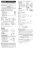
INSTRUCTION MANUAL
Photoelectric Sensor
EX-30 Series
WARNING
• Never use this product as a sensing device for personnel protection.
• In case of using sensing devices for personnel protection, use
products which meet laws and standards, such as OSHA, ANSI or IEC
etc., for personnel protection applicable in each region or country.
1CAUTIONS
2PART DESCRIPTION
No. Part Description
1Operation indicator
(orange)*1
*1For the thru-beam type sensor, located on the receiver.
Lit when the output is ON.
2Stability indicator
(green)*1
Lit when detection is stable according
to the parameters set.
3Sensitivity adjuster
*2
*2Incorporated on the emitter for EX-33 and EX-32. Not incorporated for
EX-31.
Sensing range increased when turned
clockwise.
4Operation mode
switch
EX-33
only.
• L: Light-ON
Turn the operation mode
switch fully clockwise
until it stops.
• D: Dark-ON
Turn the operation mode
switch fully
counterclockwise until it
stops.
3SENSITIVITY ADJUSTMENT
Step Sensitivity
adjuster Description
1Turn the sensitivity adjuster fully counterclock-
wise to the minimum sensitivity position.
2In the “light received” condition, turn the sen-
sitivity adjuster slowly clockwise to find point
A where the sensor output turns ON.
*1
12
3
4
L
D
L
D
MAX
MAX

2
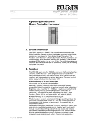
Mount the sensor on a mounting plate 3mm or less thick.
1Use the enclosed nut and toothed lock washer for mounting. The
tightening torque should be 0.6N·m or less. (For EX-32: 1N·m or less.)
2When tightening the nut, hold the sensor with your hand or an end
wrench, for example. Do not tighten the sensor itself!
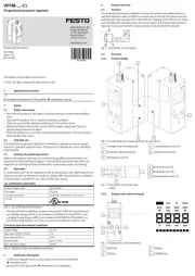
NPN output type
For the thru-beam type, the receiver incorporates the output.
PNP output type
For the thru-beam type, the receiver incorporates the output.
The slit mask is only available for the thru-beam type sensor.
The optional slit mask (OS-EX30-1) helps the sensor detect small objects.
The accuracy of the position being sensed is also increased. However, the
sensing range is reduced.
Mounting method
The tightening torque should be 0.6N·m or less.
1Insert the sensor into the mounting plate.
2Fit the washer and spacers enclosed with the slit mask.
The number of spacers required depends on the thickness of the
mounting plate.
3Mount the slit mask. Make sure that the tightening torque is 0.6N·m or
less.
For thru-beam type sensors, the P sux engraved on the sensor
denotes the emitter, e.g.. EX-
P; D denotes the receiver, e.g.
EX-
D-
.
3EX-33
In the “dark” condition, place an object to be
sensed and turn the sensitivity adjuster clock-
wise until the sensor output just turns ON.
Then turn the adjuster counterclockwise to
find point B where the sensor just turns OFF.
EX-32
In the “dark” condition, turn the sensitivity
adjuster clockwise until the sensor output
turns ON.*1
Turn it back slowly to conrm point B, where
the sensor output just turns OFF.
*1
If the sensor output does not turn ON even
when the sensitivity adjuster is turned fully
clockwise, point B is the position at MAX.
4The position exactly between points A and B
is the optimum sensing position.
*1Remember, this only applies if the operation mode is Light-ON.
4MOUNTING
5I/O CIRCUIT DIAGRAMS
Step Sensitivity
adjuster Description
MAX
MAX
3mm
+
-
±10%
Sensor circuit
Internal circuit Users' circuit
(Blue) 0V
(Black) Output (Note)
50mA max.
Load
Color code
(Brown) +V
12 to 24V DC
+
-
±10%
Color code
(Brown) +V
12 to 24V DC
50mA max.
(Black) Output (Note)
(Blue) 0V
Sensor circuit
Internal circuit Users' circuit
Load
6SLIT MASK
Mounting plate thickness No. of spacers
3mm 0
2mm 1
1mm 2
7MODELS, ORDERING INFORMATION
Mounting plate
Slit mask
Spacer
Washer
Sensor
EX-3
-
1: Thru-beam type
2: Diffuse reflective type
3: Thru-beam type / Operation mode type
Nil: NPN output type
PN: PNP output type
Nil: operation mode type
(Only EX-33□)
A: Light-ON type
B: Dark-ON type
Product specificaties
| Merk: | Panasonic |
| Categorie: | Niet gecategoriseerd |
| Model: | EX33PN |
Heb je hulp nodig?
Als je hulp nodig hebt met Panasonic EX33PN stel dan hieronder een vraag en andere gebruikers zullen je antwoorden
Handleiding Niet gecategoriseerd Panasonic

29 Juli 2025

5 Juli 2025

23 Mei 2025

16 Mei 2025

2 Mei 2025
28 April 2025

17 April 2025

17 April 2025

17 April 2025

16 April 2025
Handleiding Niet gecategoriseerd
- Voodoo Lab
- Abus
- Salewa
- REVITIVE
- Brandson
- Bravilor
- Intertechno
- U-Line
- MagTek
- Guardian
- Ariete
- Götze & Jensen
- Virax
- F2
- Truper
Nieuwste handleidingen voor Niet gecategoriseerd

2 Augustus 2025
2 Augustus 2025

1 Augustus 2025

1 Augustus 2025

1 Augustus 2025

1 Augustus 2025

1 Augustus 2025
1 Augustus 2025

1 Augustus 2025

1 Augustus 2025