Panasonic CY-111B-P Handleiding
Panasonic
Niet gecategoriseerd
CY-111B-P
Bekijk gratis de handleiding van Panasonic CY-111B-P (4 pagina’s), behorend tot de categorie Niet gecategoriseerd. Deze gids werd als nuttig beoordeeld door 202 mensen en kreeg gemiddeld 4.7 sterren uit 101.5 reviews. Heb je een vraag over Panasonic CY-111B-P of wil je andere gebruikers van dit product iets vragen? Stel een vraag
Pagina 1/4

INSTRUCTIONS
Cylindrical Photoelectric Sensor
CY-111, CY-19 CY-12 Seriesq, q
Thank you for purchasing products from Panasonic. Please read this
Instruction Manual carefully and thoroughly for the correct and optimum
use of this product. Kindly keep this manual in a convenient place for quick
reference.
WARNING
●Never use this product as a sensing device for personnel protection.
●In case of using sensing devices for personnel protection, use prod-
ucts which meet laws and standards, such as OSHA, ANSI or IEC
etc., for personnel protection applicable in each region or country.
1Cautions
●This product has been developed / produced for industrial use only.
●This product is suitable for indoor use only. The cable extension up to
a total of 10m or less with a strength of 0.34mm
2 or less (each emitter
and receiver of the thru-beam type) is possible.
●Make a cable length as short as possible to lessen noise pickup.
●Make sure that the power supply is off while wiring.
●Verify that the supply voltage including the ripple is within the rating.
●If power is supplied from a commercial switching regulator, ensure that
the frame ground (F.G.) terminal of the power supply is connected to
an actual ground.
●Shortcircuiting the load or wrong wiring may burn or damage the
product.
●Ensure that an isolation transformer is utilized for the DC power sup-
ply. If an autotransformer is utilized, the main body or power supply
may be damaged.
●If the used power supply generates a surge, connect a surge absorber
to the power supply to absorb the surge.
●Do not use the sensor during the initial transient time (0.5 sec) after
the power supply is switched on.
●Do not run the wires together with high-voltage lines or power lines
or put them in the same raceway. This can cause malfunction due to
induction.
● Avoid using the product where there are strong magnetic elds as they
may prevent the product from working according to the specication.
● Take care that the sensor is not directly exposed to a uorescent lamp
from a rapid-starter lamp or a high frequency lighting device, as it may
affect the sensing performance.
●Protect the sensor from water, oil, grease, organic solvents such as
thinner, etc., strong acid, and alkaline.
●Avoid using a product where there is excessive vapor, dust or cor-
rosive gases, or in a place where it could be exposed directly to water
or chemicals.
● This product cannot be used in an environment containing inam-
mable or explosive gases.
●Never disassemble or modify the product.
2Compliance with standards and directives
This product complies with the following standards and
regulations.
●For the EU: EMC Directive 2004/108/EC
●For the US and Canada:
ANSI/UL60947-5-2, CAN/CSA C22.2 No.14
●For Korea: S1-G-1-2009, S2-W-5-2009
* In case you require a UL listing mark or C-UL
listing mark, use a class 2 power supply unit.
RoHS directive
●This equipment complies with RoHS (CE and Chinese
directive).
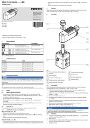
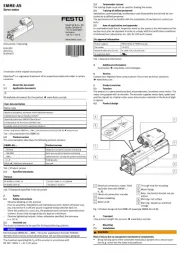
3Sensor types
Cable type (2m) Connector type (M12)
Standard
Side view
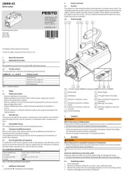
4Part description
124
3 3
1Main body
2Mounting plate
3Nut
4Cable with connector
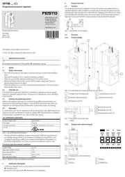
5Mounting
General installation hints
1. Attach the sensor directly on your equipment or use one of the optional
mounting brackets to x the sensor.
2. The tightening torque should be 3Nm or less.
3. If you mount a M12 connector type, you can use the optional cable with
the connector UZZ812 D. The tightening torque for the connector part qq
should be 3Nm or less.
Mounting with the mounting bracket MS-CY1-1
1. Using the holes indicated
1, screw the mounting
bracket to the surface.
2. Feed the sensor into the
mounting hole and 2
afx it with the nuts on the
sensor.
1
2
Mounting with the mounting bracket MS-CY1-2
1. Using the holes indicated
1, screw the mounting
bracket to the surface.
2. Feed the sensor into the
mounting hole and 2
adjust its direction.
3. Use the upper two screws
3 to secure the sensor.
1
3
2
1

Model no. Description
MS-CY1-1 Material: Stainless steel
MS-CY1-2 Material: Plastic (recommended for a more exible beam axis
alignment)
6Mating cables
There are two types of mating cables: straight type and elbow type. You
only need mating cables for the connector type (M12).
Straight type Elbow type
Cable type Model no. Description
Straight
UZZ81220D Length: 2m
UZZ81250D Length: 5m
Elbow
UZZ81221D Length: 2m
UZZ81251D Length: 5m
7Reectors
Square form Hexagonal form
Reective tape
Reector form Model no. Description
Square RF-420 50 x 50mm
Hexagonal RF-410 24 x 21mm
Reective tape RF-40RL5 22 x 5m, thickness: 0.4mm
8Wiring diagrams
Emitter of thru-beam type
WR9'&
±%
9LROHW,QSXW
%OXH9
%URZQ9
Receiver of thru-beam / reective type (NPN)
±%
/RDG
WR9'&
%ODFN2XWSXW
%URZQ9
%OXH9
Receiver of thru-beam / reective type (PNP)
±'&%
/RDG
WR9
%URZQ9
%OXH9
%ODFNRXWSXW
9Terminal arrangement
M12 connector
1 2
4 3
Terminal no. Function
1+V
2Input (only emitter of thru-beam type)
30V
4Output (only receiver of thru-beam and reec-
tive type)
* Make sure to insulate the ends of all unused lead wires.
10 Detection curves
Thru-beam type
15
-15
15
15 m
10 m
cm
ø 12 mm
A
A = Sensing range
Diffuse reective type
5
1 5
cm
cm
10 cm
-1
1
A
1.4
-1.4
Object 10 x 10cm; 1= White 90%, = Gray 18%2
2

Diffuse reective type with adjustable sensitivity
80
cm
cm
60 cm
1.4
-1.4
1
-1
A
Object 10 x 10cm; 1= White 90%, = Gray 18%2
Retroreective type
4
4 m
10
-4
-10
A
m4
2
cm
With reector RF-420
Retroreective type with polarizing lters
2
2 m
4
6
-2
-4
-6
m
A
3
2
cm
E/R
0.2
With reector RF-420
11 Dimensions
CY-1q
a
b
M18
Cable type Connector type
a ( b (mm) a (mm) b (mm)mm)
Standard CY-
111qqq/121 /192
46 28 60 28
Standard CY-191q48 28 62 28
Side view CY-
111V q q q/121V / 191V
/192Vq
62 28 76 28
Standard CY-122q62 44 76 44
Side view CY-122Vq78 44 92 44
Mounting bracket MS-CY1-1
35
28
50
15
20
1
20
10
= =
= =
ø18.22.5
6.5
16.5
6.5
Mounting bracket MS-CY1-2
10
45
= =
25
55
248 8
5
27
19.5
ø18.2
6.5
Reector RF-420
51
69
8
47
60
35
4 - R5
8
2 - ø
2 - ø 4.5
5.5
ø4.5
51.5
3.5
Reector RF-410
4
29
45
9
21
33
==
24
ø7.5
ø4.5
7.5
3
Product specificaties
| Merk: | Panasonic |
| Categorie: | Niet gecategoriseerd |
| Model: | CY-111B-P |
Heb je hulp nodig?
Als je hulp nodig hebt met Panasonic CY-111B-P stel dan hieronder een vraag en andere gebruikers zullen je antwoorden
Handleiding Niet gecategoriseerd Panasonic

29 Juli 2025

5 Juli 2025
23 Mei 2025
16 Mei 2025

2 Mei 2025
28 April 2025

17 April 2025

17 April 2025

17 April 2025
16 April 2025
Handleiding Niet gecategoriseerd
- Balam Rush
- Opkon
- Scale Computing
- Baracuda
- Legrand
- Physa
- Onvian
- Manhattan
- Dreame
- Hatco
- Gardenline
- Ziehl
- Petri
- Aqua-Vu
- Hobart
Nieuwste handleidingen voor Niet gecategoriseerd
2 Augustus 2025
2 Augustus 2025

1 Augustus 2025

1 Augustus 2025

1 Augustus 2025
1 Augustus 2025

1 Augustus 2025
1 Augustus 2025
1 Augustus 2025
1 Augustus 2025