Optex AX-200TN Handleiding
Optex Niet gecategoriseerd AX-200TN
Bekijk gratis de handleiding van Optex AX-200TN (8 pagina’s), behorend tot de categorie Niet gecategoriseerd. Deze gids werd als nuttig beoordeeld door 52 mensen en kreeg gemiddeld 4.1 sterren uit 4 reviews. Heb je een vraag over Optex AX-200TN of wil je andere gebruikers van dit product iets vragen? Stel een vraag
Pagina 1/8
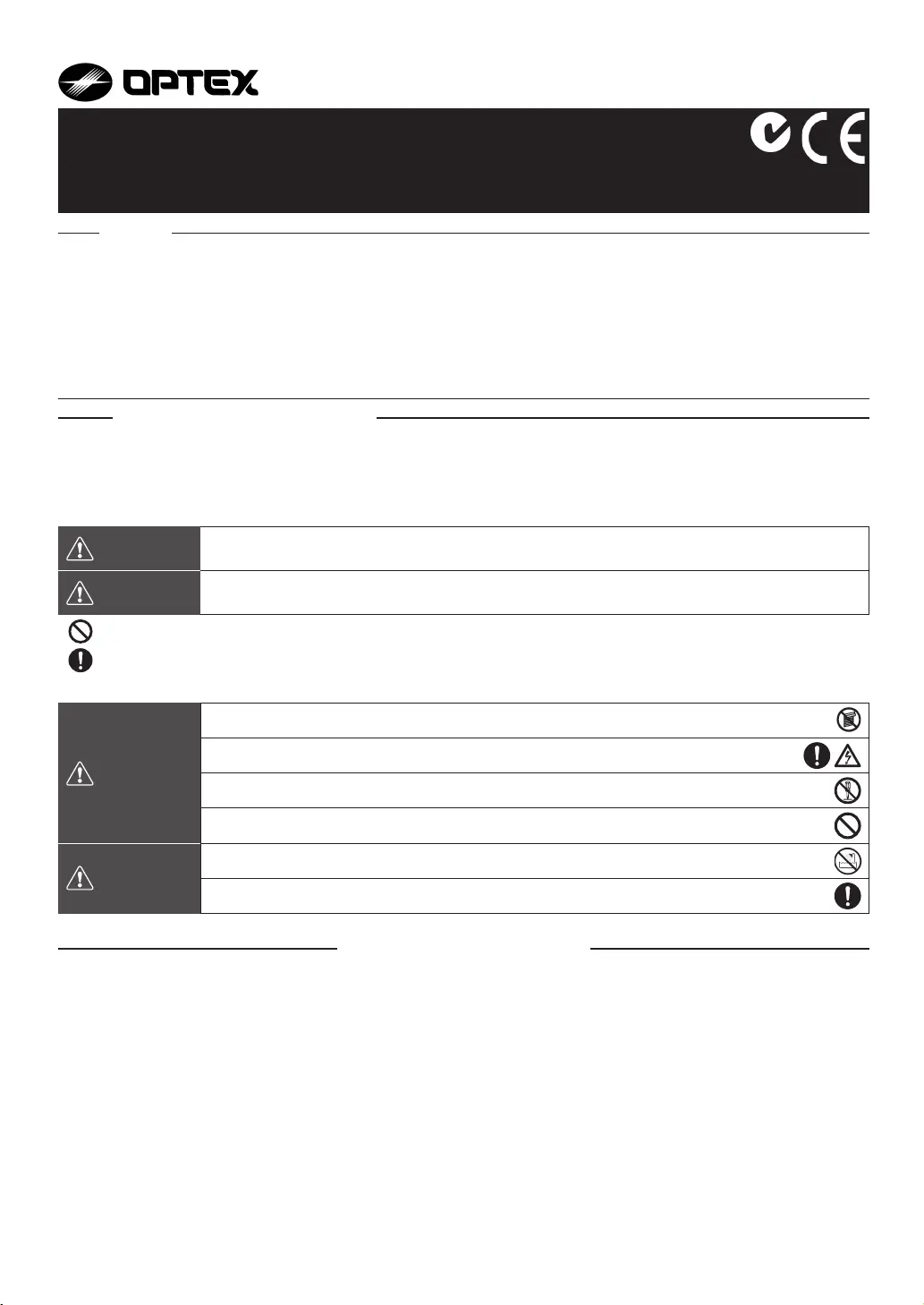
WARNING
Failure to follow the instructions provided with this indication and improper handling may cause death or
serious injury.
CAUTION
Failure to follow the instructions provided with this indication and improper handling may cause injury
and / or property damage.
WARNING
Do not use the product for purposes other than the detection of moving objects such as people and vehicles.
Do not use the product to activate a shutter, etc., which may cause an accident.
Do not touch the unit base or power terminals of the product with a wet hand (do not touch when the
product is wet with rain, etc.). It may cause electric shock.
Never attempt to disassemble or repair the product. It may cause fi re or damage to the devices.
Do not exceed the voltage or current rating specified for any of the terminals during installation, doing so
may cause fi re or damage to the devices.
CAUTION
Do not pour water over the product with a bucket, hose, etc. The water may enter, which may cause damage
to the devices.
Clean and check the product periodically for safe use. If any problem is found, do not attempt to use the
product as it is and have the product repaired by a professional engineer or electrician.
INSTALLATION MANUAL
・
Read this instruction manual carefully prior to installation.
・
After reading, store this manual carefully in an easily accessible place for reference.
・
This manual uses the following warning indications for correct use of the product and harm to you or other people and damage to
your assets, which are described below. Be sure to understand the description before reading the rest of this manual.
No. 59-1282-6 0808-20
PHOTOELECTRIC DETECTOR
AX-70TN, AX-130TN, AX-200TN
AX-100TF, AX-200TF
This symbol indicates prohibition. The specific prohibited action is provided in and/or around the fi guer.
This symbol requires an action or gives an instruction.
1. PRECAUTIONS
2. PARTS IDENTIFICATION
3. INSTALLATION
3-1 NOTE
3-2 INSTALLATION METHOD
4. WIRE CONNECTION
5. ALIGNMENT
5-1 OPTICAL ALIGNMENT
5-2 BEAM INTERRUPTION TIME
5-3 4 SELECTABLE BEAM FREQUENCIES * TF ONLY
6. WALK TEST
7. SPECIAL FUNCTION * TF ONLY
7-1 ENVIRONMENTAL DISQUALIFICATION
7-2 ALARM MEMORY
8. OPTIONAL ACCESSORIES
8-1 HEATING UNIT : HU-3
8-2 BACK COVER : BC-3
8-3 POLE SIDE COVER : PSC-3
9. TROUBLE SHOOTING
10. SPECIFICATIONS
CONTENTS
For Safe Use of the Product
< STANDARD >
< 4 SELECTABLE BEAM FREQUENCIES >
•4 selectable beam frequencies
•LED indicator for fine beam alignment level
•D.Q. circuit (Environmental disqualifi cation)
•Alarm memory
< AX-100/200TF ONLY >
•High-performance waterproof structure
•Horizontal alignment dial for user-friendliness
•Adjustable beam interruption period
•Tamper function
•Optional Accessories : Heating unit (HU-3), Back cover (BC-3),
Pole side cover (PSC-3)
•UL Listed
< AX-70/130/200TN, AX-100/200TF >
Features
N219
Product specificaties
| Merk: | Optex |
| Categorie: | Niet gecategoriseerd |
| Model: | AX-200TN |
Heb je hulp nodig?
Als je hulp nodig hebt met Optex AX-200TN stel dan hieronder een vraag en andere gebruikers zullen je antwoorden
Handleiding Niet gecategoriseerd Optex

22 December 2025
5 Juli 2025
16 Juni 2025
27 Januari 2025
21 December 2024
5 December 2024
5 December 2024
5 December 2024
5 December 2024
5 December 2024
Handleiding Niet gecategoriseerd
Nieuwste handleidingen voor Niet gecategoriseerd
2 Augustus 2026
2 Augustus 2026
2 Augustus 2026
1 Augustus 2026
31 Juli 2026
31 Juli 2026
31 Juli 2026
31 Juli 2026
31 Juli 2026
31 Juli 2026