NUVO 63/524 Handleiding
NUVO Verlichting 63/524
Bekijk gratis de handleiding van NUVO 63/524 (4 pagina’s), behorend tot de categorie Verlichting. Deze gids werd als nuttig beoordeeld door 19 mensen en kreeg gemiddeld 5.0 sterren uit 3 reviews. Heb je een vraag over NUVO 63/524 of wil je andere gebruikers van dit product iets vragen? Stel een vraag
Pagina 1/4
1
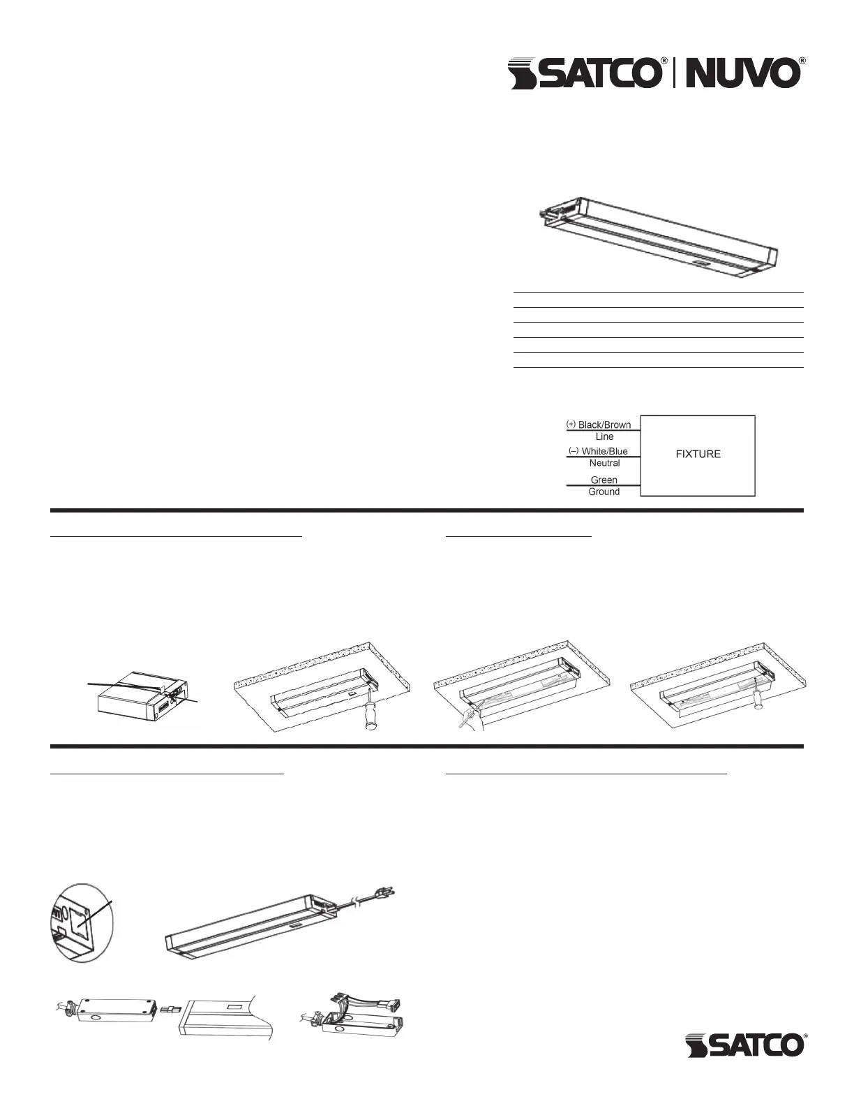
WIRING DIAGRAM
LED UNDER CABINET
FIXTURE
Models: 63-500, 63-501, 63-502, 63-503, 63-504, 63-505,
63-520, 63-521, 63-522, 63-523, 63-524, 63-525
INSTALLATION: Mounting – Direct
STEP 1: Open the two mounting screw covers located on the
front edge of the xture (A).
STEP 2: Place the xture in desired position and mount with
included screws (B).
STEP 3: Close the mounting screw cover.
Mounting – Keyhole
STEP 1: Place the xture in the desired location, open the front
panel using a at tool to pry it open, and mark the locations of the
keyholes through the wiring area (C).
STEP 2: Install (2) screws into the marked locations.
STEP 3: Mount xture through 2 keyholes on back of device.
Tighten screws if required (D).
INSTALLATION AND SAFETY INSTRUCTIONS
IMPORTANT: Read before installing xture. Retain for future reference.
Satco Products, Inc.
Brentwood, NY 11717© Copyright 2024 Satco Products, Inc. 7/24
WARNING: Risk of Fire or Electric Shock
• LED Under Cabinet Fixture installation requires knowledge of luminaries’
electrical systems. If not qualied, do not attempt installation. Contact
a qualied electrician.
• To reduce risk of re and over-heating, secure all connections.
• TURN OFF the electrical power before proceeding.
• The electrical rating of this product is 120V/60Hz.
• To prevent wiring damage or abrasion, do not expose wiring to edges
of sheet metal or other sharp objects.
• Do not make or alter any open holes in an enclosure of wiring or
electrical components during installation.
• Not rated for wet locations.
• This product must be installed in accordance with the owner’s manual,
current electrical codes and/or the current National Electric Code (NEC).
WARRANTY: This product is guaranteed for a 5-year warranty. Any
quality issue in normal use within the warranty period, will be repaired or
replaced according to the situation and under the condition specications
can be provided. Visit www.Satco.com for full warranty details and
dimmer compatibility information.
Model # (Color) Dimensions
63-500 (Wht), 63-520 (Dk Brz) 8"L x 3 1/2"W (203mm x 90mm)
63-501 (Wht), 63-521 (Dk Brz) 11"L x 3 1/2"W (280mm x 90mm)
63-502 (Wht), 63-522 (Dk Brz) 14"L x 3 1/2"W (355mm x 90mm)
63-503 (Wht), 63-523 (Dk Brz) 22"L x 3 1/2"W (559mm x 90mm)
63-504 (Wht), 63-524 (Dk Brz) 28"L x 3 1/2"W (711mm x 90mm)
63-505 (Wht), 63-525 (Dk Brz) 34"L x 3 1/2”W (863mm x 90mm)
(B)(A)
Mounting
Screw
Cover
Mounting
Screw
(C)(D)
WIRING: Option 1 – Power Cord
STEP 1: Mount the xture.
STEP 2: Remove the electrical port cover on the INPUT side.
STEP 3: Connect the power cable to the female port on the
xture.
STEP 4: Plug the power cable into a 120 Volt outlet.
STEP 5: Bundle the excess power cord with zip ties or twist ties.
Electrical Port
Cover
Option 2 – Hardwire to a Junction Box
(sold separately)
STEP 1: Disconnect power from the breaker or fuse box.
STEP 2: Remove the electrical port cover from the INPUT end.
STEP 3: Use the provided end-to-end connector or link cable
accessory to link the junction box to the INPUT side of the xture.
STEP 4: Connect the OUTPUT end of the end-to-end connector
to the junction box.
STEP 5: Open the junction box and remove the most convenient
of the three knockouts.
STEP 6: Mount the junction box and the xture to the cabinet.
STEP 7: Attach the 3/8" die-cast connector to the junction box
and pull wiring through it.
STEP 8: Connect wiring using above wiring diagram.
STEP 9: Close the junction box.
End-to-End Connector
Product specificaties
| Merk: | NUVO |
| Categorie: | Verlichting |
| Model: | 63/524 |
Heb je hulp nodig?
Als je hulp nodig hebt met NUVO 63/524 stel dan hieronder een vraag en andere gebruikers zullen je antwoorden
Handleiding Verlichting NUVO

14 Maart 2026
13 Maart 2026
13 Maart 2026
12 Maart 2026
30 December 2026
30 December 2026
30 December 2026
30 December 2026
29 December 2026
29 December 2026
Handleiding Verlichting
Nieuwste handleidingen voor Verlichting
30 Juni 2026
30 Juni 2026
30 Juni 2026
30 Juni 2026
30 Juni 2026
29 Juni 2026
29 Juni 2026
29 Juni 2026
29 Juni 2026
26 Juni 2026