NuTone ChromaComfort Handleiding
NuTone Ventilator ChromaComfort
Bekijk gratis de handleiding van NuTone ChromaComfort (8 pagina’s), behorend tot de categorie Ventilator. Deze gids werd als nuttig beoordeeld door 70 mensen en kreeg gemiddeld 4.1 sterren uit 7 reviews. Heb je een vraag over NuTone ChromaComfort of wil je andere gebruikers van dit product iets vragen? Stel een vraag
Pagina 1/8
1
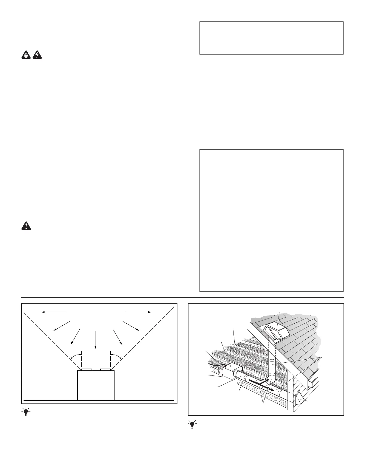
OPTION - To mount housing anywhere between ceiling framing:
Use optional Hanger Bar Kit (sold separately from local distributors
or website). Follow mounting instructions included with kit.
ROOF CAP* (with built-in damper)
WALL CAP*
(with built-in
damper)
4-IN. ROUND
ELBOWS*
FAN
HOUSING
Seal gaps
around
housing.
Seal duct joints
with tape.
INSULATION
(Place around and
over fan housing.)
POWER
CABLE *
* Purchase separately.
OR
Keep duct
runs short.
4-IN. ROUND
DUCT*
IMPORTANT -
The ducting from this fan to the outside of the building
has a strong effect on the air flow, noise and energy use of the fan. Use
the shortest, straightest duct routing possible for best performance, and
avoid installing the fan with smaller ducts than recommended. Insulation
around the ducts can reduce energy loss and inhibit mold growth. Fans
installed with existing ducts may not achieve their rated airflow.
WARNING
TO REDUCE THE RISK OF FIRE, ELECTRIC SHOCK, OR INJURY TO PERSONS,
OBSERVE THE FOLLOWING:
1. Use this unit only in the manner intended by the manufacturer. If you have
questions, contact the manufacturer at the address or telephone number listed
in the warranty.
2. Before servicing or cleaning unit, switch power off at service panel and lock
the service disconnecting means to prevent power from being switched on
accidentally. When the service disconnecting means cannot be locked, securely
fasten a prominent warning device, such as a tag, to the service panel.
3. Installation work and electrical wiring must be done by a qualified person(s)
in accordance with all applicable codes and standards, including fire-rated
construction codes and standards.
4. Sufficient air is needed for proper combustion and exhausting of gases through
the flue (chimney) of fuel burning equipment to prevent backdrafting. Follow
the heating equipment manufacturer’s guideline and safety standards such as
those published by the National Fire Protection Association (NFPA), and the
American Society for Heating, Refrigeration and Air Conditioning Engineers
(ASHRAE), and the local code authorities.
5. When cutting or drilling into wall or ceiling, do not damage electrical wiring
and other hidden utilities.
6. Ducted fans must always be vented to the outdoors.
7. Acceptable for use over a tub or shower when connected to a GFCI (Ground
Fault Circuit Interrupter) - protected branch circuit (ceiling installation only).
8. This unit must be grounded.
CAUTION
1. For general ventilating use only. Do not use to exhaust hazardous or explosive
materials and vapors.
2. This product can be installed in a wall if mounted 8-ft. or more above the floor.
3. To avoid motor bearing damage and noisy and/or unbalanced impellers, keep
drywall spray, construction dust, etc. off power unit.
4. Please read specification label on product for further information and
requirements.
READ AND SAVE THESE INSTRUCTIONS
Cooking
Equipment
Floor
COOKING AREA
Do not install above or
inside this area.
45
o
45
o
NOT FOR USE IN
A COOKING AREA.
CLEANING & MAINTENANCE
For quiet and efficient operation, long life, and attractive appearance
- lower or remove grille and vacuum interior of unit with the dusting
brush attachment.
The motor is permanently lubricated and never needs oiling. If the
motor bearings are making excessive or unusual noises, replace the
blower assembly (includes motor and impeller).
OPERATION
The Chroma Fan/Light must be operated using only the wall control
included. See separate operating instructions. DO NOT operate the
Chroma Fan/Light with any other switches or controls.
For Warranty Statement, Service Parts, Technical Support, or to
Register your product, please visit our website or call:
In the United States - Broan.com 800-637-1453 or NuTone.com
888-336-6151. In Canada - Broan.ca or NuTone.ca 877-896-1119
ChromaComfort
TM
Fan/Light Installation
The Bluetooth
®
word mark and logos are registered trademarks owned by Bluetooth
®
SIG,
Inc. and any use of such marks by Broan-NuTone LLC is under license. Other trademark and
trade names are those of their respective owners.
NOTE: This equipment has been tested and found to comply with the limits for a Class
B digital device, pursuant to Part 15 of the FCC Rules. These limits are designed to
provide reasonable protection against harmful interference in a residential installation.
This equipment generates, uses and can radiate radio frequency energy and, if not
installed and used in accordance with the instructions, may cause harmful interference
to radio communications. However, there is no guarantee that interference will not occur
in a particular installation. If this equipment does cause harmful interference to radio or
television reception, which can be determined by turning the equipment off and on, the user
is encouraged to try to correct the interference by one or more of the following measures:
• Reorient or relocate the receiving antenna.
• Increase the separation between the equipment and receiver.
• Connect the equipment into an outlet on a circuit different from that to which the receiver
is connected.
• Consult the dealer or an experienced radio/TV technician for help.
This device complies with Part 15 of the FCC Rules and RSS-210 of Canada. Operation is
subject to the following two conditions:
(1) This device may not cause interference, and (2) this device must accept any interference
received, including interference that may cause undesired operation. FCC IDs: 2ADLL-
RGB001 & 2ADLL-RGB002 IC IDs: 2143B-RGB001 & 2143B-RGB002
This Bluetooth
®
wireless technology enabled luminaire complies with FCC radiation
exposure limits set forth for an uncontrolled environment. End users must follow the
specific operating instructions for satisfying exposure compliance. This luminaire must not
be co-located or operate in conjunction with any other antenna or transmitter.
Changes or modifications not expressly approved by the party responsible for compliance
could void the user’s authority to operate the equipment.
Product specificaties
| Merk: | NuTone |
| Categorie: | Ventilator |
| Model: | ChromaComfort |
Heb je hulp nodig?
Als je hulp nodig hebt met NuTone ChromaComfort stel dan hieronder een vraag en andere gebruikers zullen je antwoorden
Handleiding Ventilator NuTone

17 April 2025
16 April 2025
16 April 2025
16 April 2025
16 April 2025
16 April 2025
16 April 2025
16 April 2025
16 April 2025
16 April 2025
Handleiding Ventilator
Nieuwste handleidingen voor Ventilator
14 Februari 2026
14 Februari 2026
13 Februari 2026
13 Februari 2026
13 Februari 2026
13 Februari 2026
12 Februari 2026
11 Februari 2026
11 Februari 2026
11 Februari 2026