Nitek MM-100 Handleiding
Nitek Mediaspeler MM-100
Bekijk gratis de handleiding van Nitek MM-100 (3 pagina’s), behorend tot de categorie Mediaspeler. Deze gids werd als nuttig beoordeeld door 166 mensen en kreeg gemiddeld 4.1 sterren uit 2 reviews. Heb je een vraag over Nitek MM-100 of wil je andere gebruikers van dit product iets vragen? Stel een vraag
Pagina 1/3
/ /
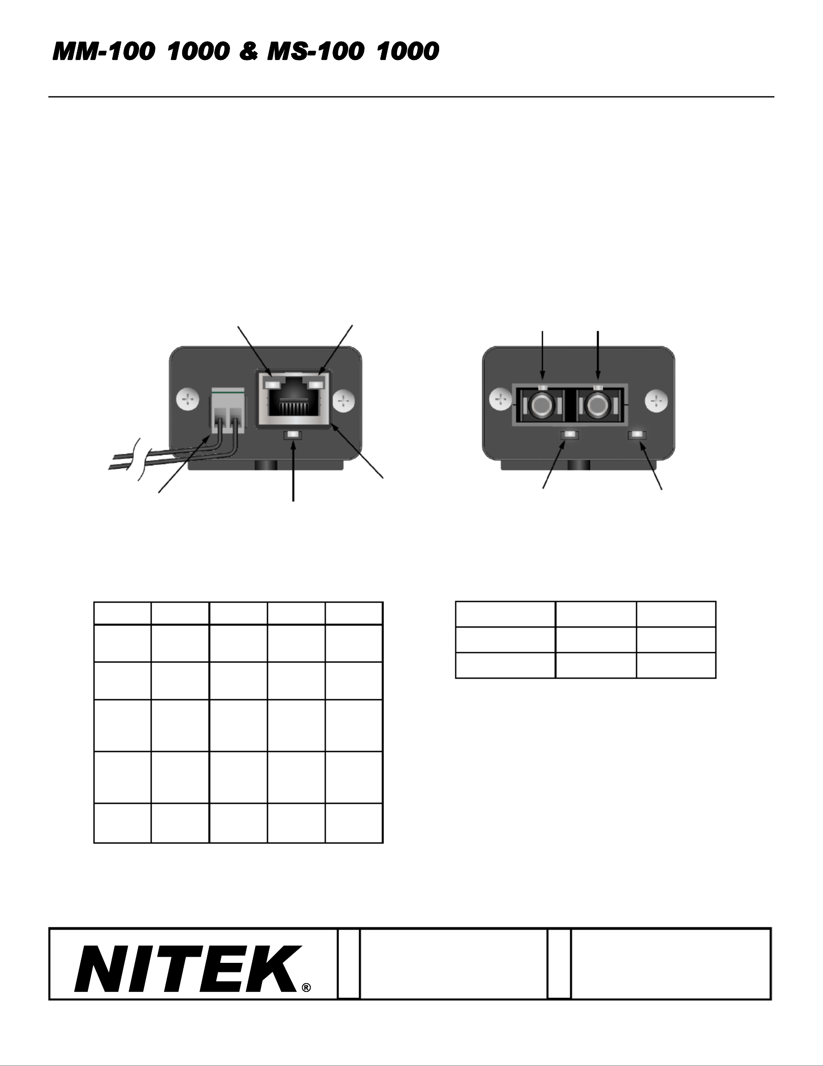
10/100/1000 MEDIA CONVERTERS w/PoE Option
Introducon
This manual applies to the following media converters.
MM MS- - 100: MulMode SC, 10/100 Mbps - - 100: SingleMode SC, 10/100 Mbps
MM MS- - 1000: MulMode SC, 10/100/1000 Mbps - - 1000: SingleMode SC, 10/100/1000 Mbps
MM MS-100- - POE: MulMode SC, 10/100 Mbps, 30W PoE-100- - POE: SingleMode SC, 10/100 Mbps, 30W PoE
De Aar 99
8253 PN Dronten
The Netherlands
Tel: +31(0) 321 310 043
Email: [email protected]t-
WWW.NITEK.NET
USA
5410 Newport Drive, # 24
Rolling Meadows, IL 60008
Phone: (847) 259-8900
Fax: (847) 259-1300
Email: [email protected] -
WWW.NITEK.NET
EUROPE
20171128
RJ45 SideOpcal Side
680700106
TX RX
PoE LED
(on POE Models)
Opcal
Link LED
Device
Power LED
Power
Jack
RJ45
Jack
1000 Mbps
Link LED
10/100 Mbps
Link LED
LEDGREEN ORANGEBLINKOFF
DEVICE
POWER
NO
POWERPOWER N/AN/A
OPTICAL
LINK
NO
LINKLINKED N/AN/A
10/100
Mbps
LINK
NO
LINK
100
Mbps
LINK
10
Mbps
LINK
ACTIVE
LINK
1000
Mbps
LINK
NO
LINK
1000
Mbps
LINK
N/AACTIVE
LINK
PoEPoE
OFF
PoE
ONN/APoE
FAULT
MODELSDC INPUT*AC INPUT
Non- PoE 6 6-16V-12V
PoE48- 56V N/A
LED FUNCTIONSPOWER JACK OPTIONS
*POLARITY NOT IMPORTANT DUE TO INTERNAL BRIDGE
Installation and
Operation Manual
Product specificaties
| Merk: | Nitek |
| Categorie: | Mediaspeler |
| Model: | MM-100 |
Heb je hulp nodig?
Als je hulp nodig hebt met Nitek MM-100 stel dan hieronder een vraag en andere gebruikers zullen je antwoorden
Handleiding Mediaspeler Nitek

4 Juni 2023
Handleiding Mediaspeler
Nieuwste handleidingen voor Mediaspeler
12 Mei 2026
11 Mei 2026
30 April 2026
28 Maart 2026
13 Maart 2026
27 Februari 2026
20 Januari 2026
14 Januari 2026
27 December 2025
22 December 2025