Netgear GS305Pv3 Handleiding


Lees hieronder de đź“– handleiding in het Nederlandse voor Netgear GS305Pv3 (2 pagina's) in de categorie Niet gecategoriseerd. Deze handleiding was nuttig voor 16 personen en werd door 2 gebruikers gemiddeld met 4.5 sterren beoordeeld

Pagina 1/2
Installation Guide
5-Port PoE+ Gigabit Ethernet SOHO
Unmanaged Switch (63W)
Model GS305Pv3
Package contents
• Switch model GS305Pv3
• DC power adapter
• Detachable power cable (varies by region)
• Wall-mount kit screws
• Four rubber footpads
• Installation guide
NOTE: We recommend that you use a Category 5e (Cat 5e) cable or a higher rated cable
for Gigabit Ethernet connections.
This switch is designed for indoor use only. If you want to connect it to a device located
outdoors, the outdoor device must be properly grounded and surge protected, and you
must install an Ethernet surge protector inline between the switch and the outdoor device.
Failure to do so can damage the switch.
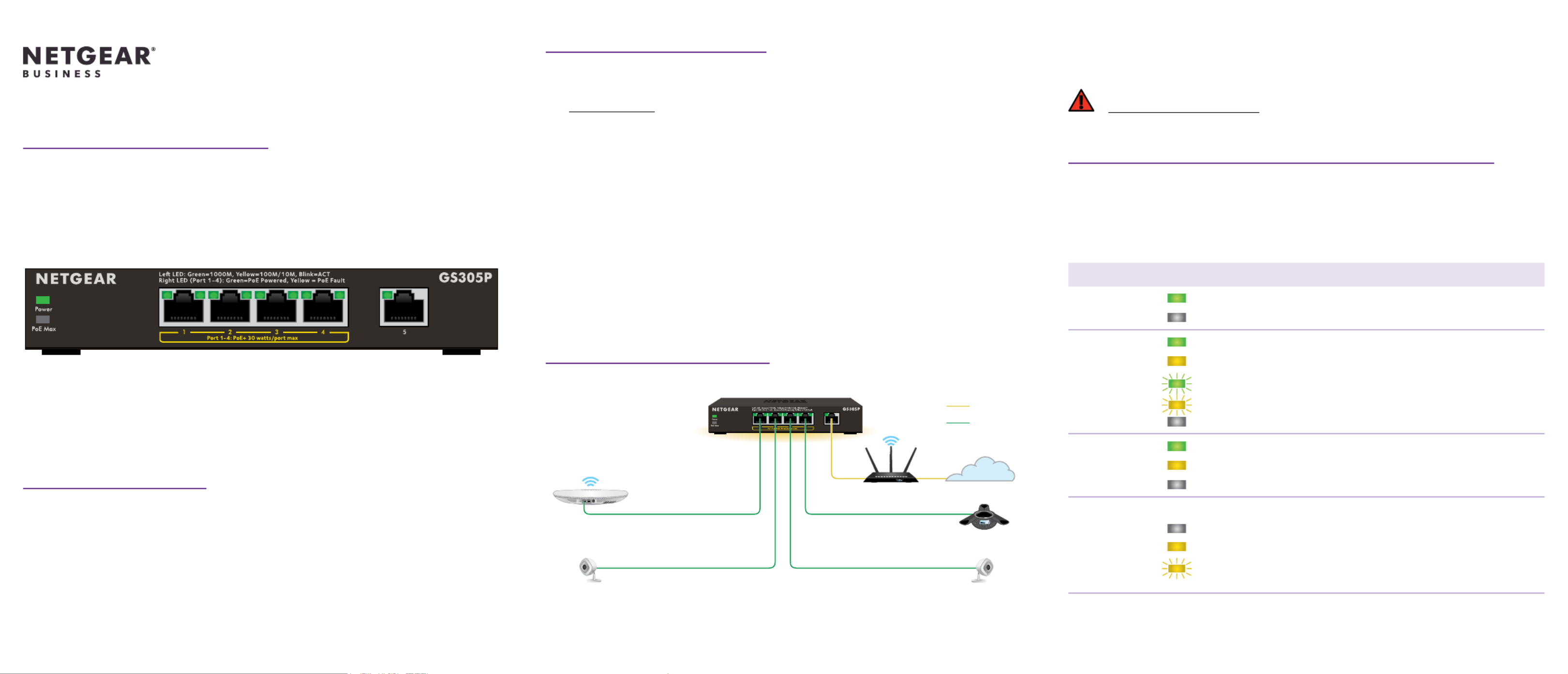
3. Connect to power and check the LEDs
When you connect the power adapter to the switch and plug the power cable into an
electrical outlet, the LEDs indicate the status.
Model GS305Pv3 provides PoE+ or PoE power on ports 1–4 up to 30W PoE to each port,
with a PoE power budget of 63W across all active PoE ports.
LED Description
Power LED . The switch is receiving power. On
Off. The switch is not receiving power.
Ports 1–5
left LED
On.1000 Mbps link on this port.
. 100 Mbps or 10 Mbps link on this port.On
Blinking. 1000 Mbps activity on this port.
Blinking. 100 Mbps or 10 Mbps activity on this port.
Off. No link is detected on this port.
Ports 1–4
right LED
On. PoE is in use.
. PoE fault. On
Off. PoE is not in use on this port.
PoE Max LED The PoE Max LED indicates the status of the PoE budget on the switch:
Off. Sufîť´cient. More than 7W of PoE power is available.
On. Less than 7W of PoE power is available.
Blinking. At least once during the previous two minutes, less
than 7W of PoE power was available.
1. Register the switch
We recommend that you register your switch
1. From a computer or mobile device that is connected to the Internet, visit
my.netgear.com.
2. Log in to your NETGEAR account.
NOTE: If you don’t have a free NETGEAR account, you can create one.
The My Products page displays.
3. From the menu on the left, select Register a Product.
4. In the Serial Number îť´eld, type the serial number of your switch.
The serial number is 13 digits long. It is printed on the switch label.
5. From the Date of Purchase menu, select the date that you purchased the switch.
6. Click the button.REGISTER
Your switch is registered to your NETGEAR account.
A conîť´rmation email is sent to your NETGEAR account email address.
2. Connect the switch
Sample connections
Access point
Security cameras
VoIP phone
Router Internet
GS305Pv3
Internet
PoE+
Before connecting this switch to outdoor cables or devices, see
kb.netgear.com/000057103 for safety and warranty information.
NETGEAR, Inc.
350 East Plumeria Drive
San Jose, CA 95134, USA
NETGEAR INTERNATIONAL LTD
Floor 1, Building 3,
University Technology Centre
Curraheen Road, Cork,
T12EF21, Ireland
© NETGEAR, Inc., NETGEAR and the NETGEAR Logo
are trademarks of NETGEAR, Inc. Any non‑NETGEAR
trademarks are used for reference purposes only.
Support and Community
Visit netgear.com/support to get your questions answered and access the latest
downloads.
You can also check out our NETGEAR Community for helpful advice at community.
netgear.com.
Regulatory and Legal
Si ce produit est vendu au Canada, vous pouvez accéder à ce document en français
canadien Ă  https://www.netgear.com/support/download/.
(If this product is sold in Canada, you can access this document in Canadian French at
https://www.netgear.com/support/download/.)
For regulatory compliance information including the EU Declaration of Conformity, visit
https://www.netgear.com/about/regulatory/.
See the regulatory compliance document before connecting the power supply.
For NETGEAR’s Privacy Policy, visit https://www.netgear.com/about/privacy-policy.
By using this device, you are agreeing to NETGEAR’s Terms and Conditions at
https://www.netgear.com/about/terms-and-conditions. If you do not agree, return the
device to your place of purchase within your return period.
Do not use this device outdoors. The PoE source is intended for intra building connection
only.
Applicable to 6 GHz devices only: Only use the device indoors. The operation of 6 GHz
devices is prohibited on oil platforms, cars, trains, boats, and aircraft, except that operation
of this device is permitted in large aircraft while îťµying above 10,000 feet. Operation of
transmitters in the 5.925-7.125 GHz band is prohibited for control of or communications
with unmanned aircraft systems.
PoE considerations
The PoE and PoE+ power supplied by the switch is prioritized in ascending port order
(from port 1 to port 4), with a total power budget of 63W for the GS305Pv3. If the power
requirements for the attached powered devices (PDs) exceed the total power budget of
the switch, the PD on the highest-numbered port is disabled to make sure that the PDs
that are connected to the higher-priority, lower-numbered ports are supported îť´rst.
PoE troubleshooting
Here are some tips for correcting PoE problems that might occur:
• If the PoE Max LED is yellow, disconnect one or more PoE devices to prevent PoE
oversubscription. Start by disconnecting the device from the highest-numbered port.
• For each powered device (PD) that is connected to the switch, the associated right
port LED on the switch lights solid green. If the right port LED lights yellow, a PoE fault
occurred because of one of the conditions listed in the following table.
PoE Fault Condition Possible Solution
A PoE-related short circuit occurred on the port. The problem is most likely with
the attached PD. Check the
condition of the PD, or restart
the PD by disconnecting and
reconnecting the PD.
The PoE power demand of the PD exceeded
the maximum level that the switch permits. The
maximum level is 15.4W for a PoE connection or
30W for a PoE+ connection
The PoE current on the port exceeded the
classiîť´cation limit of the PD.
The PoE voltage of the port is outside the range
that the switch permits
Power cycle the switch to see if
the condition resolves itself.
Mount the switch on a wall
We recommend that you use the wall-mount screws that came with the switch.
1. Locate the two mounting holes on the bottom panel of the switch.
2. Mark and drill two mounting holes in the wall.
3. The two mounting holes must be 3.19 in. (80 mm) apart, center-to-center. Insert the
supplied anchors into the wall and tighten the screws with a No. 2 Phillips screwdriver.
Leave about 0.125 in. (4 mm) of each screw protruding from the wall so that you can
insert the screw heads into the holes on the bottom panel.
NOTE: The screws are 3 mm in diameter, 25 mm in length.
Specications
Speciîť´cation Description
Network interface RJ-45 connector for 1000BASE-T, 100BASE-TX, or 10BASE-T
Network cable Category 5 (Cat 5) or higher rated Ethernet cable
Ports 5 total. Ports 1-4 can provide PoE+; Port 5 is an uplink port.
Power adapter 54V @ 1.25A DC input
Power consumption 67.5W maximum; 1.02W standby
PoE power budget 30W maximum per PoE+ port with a total PoE power budget
of 63W for the switch
Dimensions (W x D x H) 6.2 x 4.0 x 1.1 in. (158 x 101 x 27 mm)
Weight 0.88 lb (0.40 kg)
Operating temperature 32–104°F (0–40°C)
Operating humidity 10%–90% relative humidity, noncondensing
August 2022


Product specificaties

Merk: Netgear
Categorie: Niet gecategoriseerd
Model: GS305Pv3

Heb je hulp nodig?

Als je hulp nodig hebt met Netgear GS305Pv3 stel dan hieronder een vraag en andere gebruikers zullen je antwoorden


Handleiding Niet gecategoriseerd Netgear

Handleiding Niet gecategoriseerd

Nieuwste handleidingen voor Niet gecategoriseerd