Microchip USB4715 Handleiding
Microchip
Niet gecategoriseerd
USB4715
Bekijk gratis de handleiding van Microchip USB4715 (20 pagina’s), behorend tot de categorie Niet gecategoriseerd. Deze gids werd als nuttig beoordeeld door 17 mensen en kreeg gemiddeld 4.4 sterren uit 9 reviews. Heb je een vraag over Microchip USB4715 of wil je andere gebruikers van dit product iets vragen? Stel een vraag
Pagina 1/20

2017-2018 Microchip Technology Inc. DS00002430C-page 1
INTRODUCTION
The USB-to-SPI Bridging feature gives system designers using Microchip hubs expanded system control and potential
BOM reduction. The use of a separate USB-to-SPI device is no longer required, and a downstream USB port is not lost
as occurs when a standalone USB-to-SPI device is implemented. This feature is available on Microchip hubs which con-
tain the internal Hub Feature Controller and an SPI interface. These hubs include USB4712, USB4714, USB4715,
USB4912, USB4914, USB4916, USB4925, and USB4927.
Commands may be sent from the USB Host to the internal Hub Feature Controller (HFC) device in the Microchip hub
to perform the following functions:
• Get hub information
• Reset the hub
• Force boot from internal ROM
• Enable SPI pass-through interface
• Disable SPI pass-through interface
• SPI pass-through write/read
SECTIONS
General Information
Part Number-Specific Information
Microchip Software Solutions
Low-Level Implementation
REFERENCES
Consult the following documents for details on the specific parts referred to in this document:
• USB4712 Data Sheet
• USB4714 Data Sheet
• USB4715 Data Sheet
• USB4912 Data Sheet
• USB4914 Data Sheet
• USB4916 Data Sheet
• USB4925 Data Sheet
• USB4927 Data Sheet
• SST26VF016B Data Sheet
• Configuration of the USB471x and USB49xx Application Note
AN2430
USB-to-SPI Bridging with Microchip USB471x and
USB49xx Hubs
Author: Shiva Balasubramanian
Microchip Technology Inc.
AN2430
DS00002430C-page 2 2017-2018 Microchip Technology Inc.
GENERAL INFORMATION
The USB-to-SPI Bridging features in Microchip hubs work via host commands sent to a Hub Feature Controller embed-
ded within the hub located on an additional internal USB port. In order for the bridging features to work correctly, this
Internal Hub Feature Controller must be enabled by default. The SPI interface is always enabled after reset. It can be
disabled by setting the SPI_MASTER_DIS bit in the PAD_MUX_CTL register. See Table 1 below for details on default
Hub Feature Controller settings by part number.
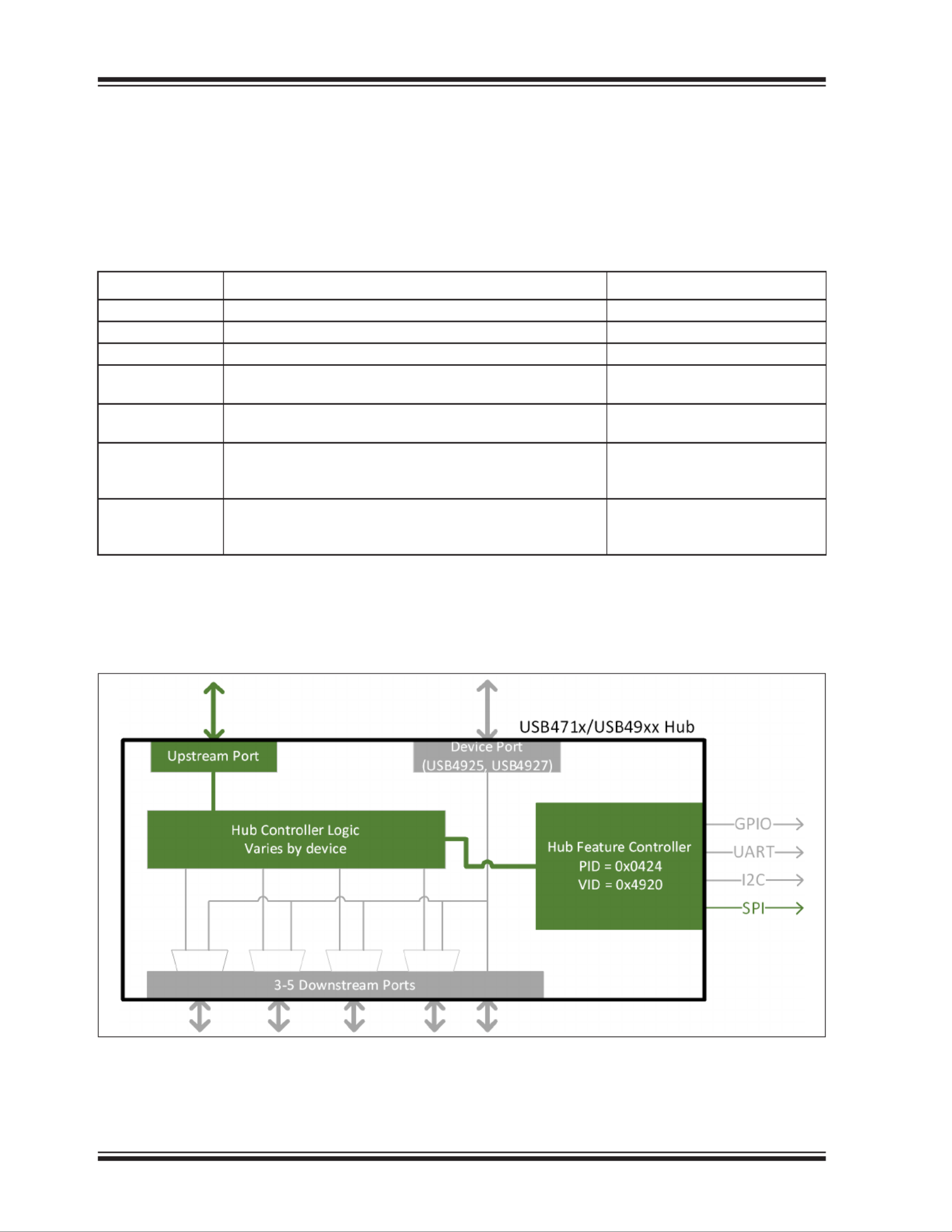
TABLE 1: DEFAULT SETTINGS FOR HUB FEATURE CONTROLLER ENABLE
Part Number Part Summary Hub Controller Default Setting
USB4712 One USB upstream port and one USB Flex port Enabled
USB4715 One USB upstream port and four USB Flex ports Enabled
USB4912 One USB upstream port and two USB CarPlay ports Enabled
USB4914 One USB upstream port, two USB CarPlay ports,
and one non-removable standard USB port
Enabled
USB4916 One USB upstream port, four USB CarPlay ports, and one
non-removable standard USB port
Enabled
USB4925 One USB upstream port, one secondary USB downstream
port, two USB CarPlay ports, and one non-removable stan-
dard USB port
Enabled
USB4927 One USB upstream port, one secondary USB downstream
port, four USB CarPlay ports, and one non-removable stan-
dard USB port
Enabled
The Hub Feature Controller is connected to an extra internal port in the hub. (See Figure 1.) For example, in a four-port
hub, the Hub Feature Controller is connected to port 5. The Product ID (PID) varies as per the SKU selected. All bridging
commands are addressed to the Hub Feature Controller and not the hub.
FIGURE 1: MICROCHIP HUB FEATURE CONTROLLER BLOCK DIAGRAM

2017-2018 Microchip Technology Inc. DS00002430C-page 3
AN2430
SPI Bridging Commands
The following SPI functions are supported:
•Get Hub Information
•Reset the Hub
•Force Boot from Internal ROM
•Disable the SPI Pass-Through Interface
•Enable the SPI Pass-Through Interface
•SPI Pass-Through Write/Read
GET HUB INFORMATION
The host can get information about the hub by issuing the GET_HUB_INFO command. In response, the hub sends a
packet which contains information about the device revision, firmware version, and boot mode.
RESET THE HUB
The host can soft reset the hub externally by issuing CMD_DEV_RESET command. This forces the hub firmware to
start execution from 0x000000 and go through the boot sequence again.
FORCE BOOT FROM INTERNAL ROM
In cases where the hub is executing out of an external SPI ROM and the host wants to perform SPI pass-through
transfers with the SPI ROM, this command sequence can be used to force the hub to boot and execute from the internal
ROM.
ENABLE THE SPI PASS-THROUGH INTERFACE
To acquire the SPI interface, the host must send a CMD_SPI_ENTER_PASSTHRU SETUP packet before performing
any SPI Write/Read commands. The SPI interface may operate at either 30 MHz or 60 MHz (based on pin strapping).
DISABLE THE SPI PASS-THROUGH INTERFACE
The SPI pass-through interface can be disabled after read/write operations by sending a CMD_SPI_EXIT_PASSTHRU
SETUP packet.
SPI PASS-THROUGH WRITE/READ
The SPI pass-through interface allows single/multi-byte write access and read access. In case of these operations, the
SPI interface functions as a complete pass-through, which means any SPI data sent as a payload in the USB transfer
gets transferred on to the SPI lines directly. Therefore, the host must properly arrange data payloads in the appropriate
SPI-compatible format and bit order, including the SPI slave device address. Up to 256 bytes can be written to an SPI
peripheral using an SPI Write command sequence.
Data can also be read from an SPI peripheral using a combination of SPI write/read pass-through transfers. The host
first needs to send a SETUP packet which informs the hub about the number of bytes to be read. Following this com-
mand, the requested data bytes are stored by the hub in an internal register at 0xBFD22310. The SPI Read command
sequence can then be initiated by the host to retrieve the data. Up to 512 bytes of data can be read per SPI Read com-
mand sequence.
SPI Interface SETUP Requirements
SPI MASTER INTERFACE
The SPI interface always acts as an SPI master.
SELECTING SPI FREQUENCY
The SPI interface may operate at either 30 MHz or 60 MHz. The speed is selected by pin strapping the SPI_SD_SEL
pin (which is the SPI_DO pin during runtime) and is detected at power-on or at the end of reset. The strapping options
are:
• GND (Logical ) = 30 MHz0
• 3.3V (Logical ) = 60 MHz1
Product specificaties
| Merk: | Microchip |
| Categorie: | Niet gecategoriseerd |
| Model: | USB4715 |
Heb je hulp nodig?
Als je hulp nodig hebt met Microchip USB4715 stel dan hieronder een vraag en andere gebruikers zullen je antwoorden
Handleiding Niet gecategoriseerd Microchip
14 Mei 2025
6 Mei 2025

6 Mei 2025

6 Mei 2025

6 Mei 2025

6 Mei 2025

6 Mei 2025

6 Mei 2025

6 Mei 2025

6 Mei 2025
Handleiding Niet gecategoriseerd
- Walkstool
- Mercusys
- ALLO
- Hurricane
- Goliath
- Omega Altise
- Yato
- Stiga
- Bixolon
- Sunny
- POWEROWL
- Elite Force
- GRAUGEAR
- South Shore
- Saki
Nieuwste handleidingen voor Niet gecategoriseerd

17 September 2025

17 September 2025

17 September 2025

17 September 2025

17 September 2025

17 September 2025

17 September 2025

17 September 2025

17 September 2025

17 September 2025