Lutron AY2-LFSQ Handleiding
Lutron Niet gecategoriseerd AY2-LFSQ
Bekijk gratis de handleiding van Lutron AY2-LFSQ (2 pagina’s), behorend tot de categorie Niet gecategoriseerd. Deze gids werd als nuttig beoordeeld door 10 mensen en kreeg gemiddeld 4.8 sterren uit 3 reviews. Heb je een vraag over Lutron AY2-LFSQ of wil je andere gebruikers van dit product iets vragen? Stel een vraag
Pagina 1/2
Fan / Light Controls
Rated at 120V~ 60Hz
AY2-LFSQ: Fan: 1.5A Light: 300W S2-LF:Fan: 2.5A Light: 300W
TG2-LFSQ: Fan: 1.5A Light: 300W S2-LFSQ: Fan: 1.5A Light: 300W
S2W-LFSQ: Fan: 1.5A Light: 300W
Important Notes | Please read before installing.
1.NOTICE: To avoid overheating and possible damage to other equipment, do not use
to control receptacles, fluorescent lighting fixtures, or transformer-supplied appliances.
2.Controls require separate wires in the wallbox for fan and light.
3.For new installations, wire a test switch before installing the control.
4.Set multispeed fans to their highest setting before installing controls.
5.Use an AY2-LFSQ, S2-LFSQ, S2W-LFSQ or TG2-LFSQ control with a ceiling paddle fan
only. Use only one ceiling paddle fan per control.
6.Use an S2-LF only with fans marked “Suitable for use with solid-state fan-speed controls.”
7.Controls may feel warm to the touch during normal operation.
8.Grounding: When no “grounding means” exist in wallbox, the 2011 National Electrical
Code
® (NEC®) allows a control to be installed as a replacement if 1) a nonmetallic, non-
combustible faceplate is used with nonmetallic attachment screws or 2) the circuit is
protected by a ground fault circuit interrupter (GFCI). When installing a control according to
these methods, cap or remove green wire before screwing control into wallbox.
9.The use of ceiling fan controls on circuits protected by a ground fault circuit interrupter
(GFCI) may result in nuisance tripping and is not recommended.
10. Install in accordance with all national and local electrical codes.
11. Clean control with a soft damp cloth only. Do not use any chemical cleaners.
Multi-Unit Installations
When combining controls in a wallbox, remove all inner side sections before wiring
(see below). Use pliers to bend each side section up and down until it breaks off. S2-LF
controls require reduction of their capacity. Refer to chart below for maximum capacity.
Other fan-speed controls (-LFSQ) do not require capacity reduction.
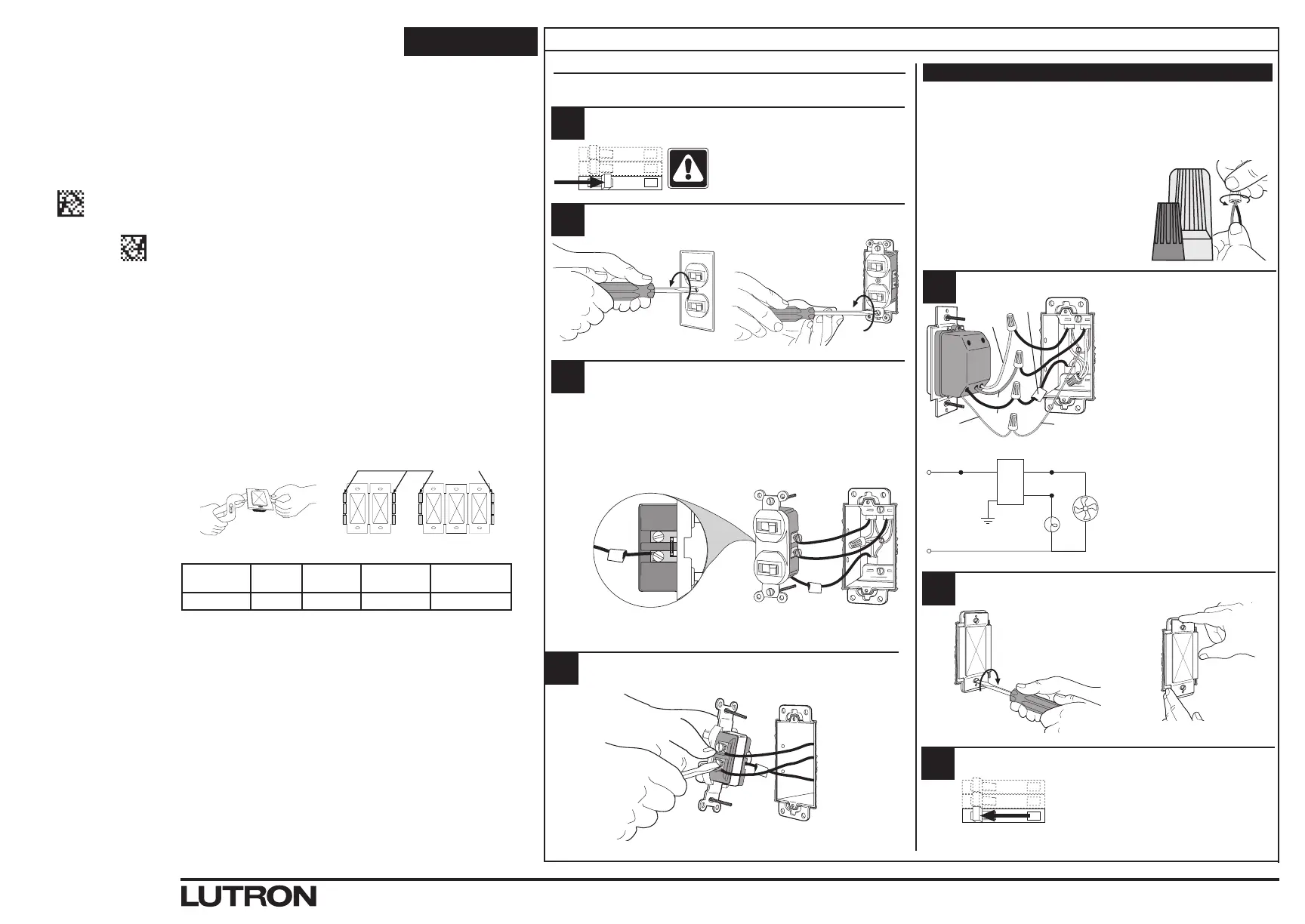
Installation
For installations involving more than one control in a wallbox, refer to Multi-Unit
Installations before beginning.
Turn power OFF at circuit break er or remove fuse.
Remove switch mounting screws. Pull switch from wall.
Verify application. This control mounts in a single-gang wallbox and independently
controls a ceiling paddle fan and a light with each slider. Independent wire must
be provided for the fan and light in addition to the feed wire (Live).
Disconnect switch wires.
Lutron Electronics Co., Inc.
7200 Suter Road, Coopersburg, PA 18036-1299, U.S.A.
P/N 0301992 Rev. A 03/2021
To Fan
Turn screws to loosen.
To Light
Align control and
tighten screws.
ON
OFF
ON
OFF
ON
OFF
Start screws.
Limited Warranty
(Valid only in U.S.A., Canada, Puerto Rico, and the Caribbean.)
Lutron will, at its option, repair or replace any unit that is defective in materials or manufacture within one
year after purchase. For warranty service, return unit to place of purchase or mail to Lutron at 7200 Suter
Rd., Coopersburg, PA 18036-1299, postage pre-paid.
THIS WARRANTY IS IN LIEU OF ALL OTHER EXPRESS WARRANTIES, AND THE IMPLIED WARRANTY OF
MERCHANTABILITY IS LIMITED TO ONE YEAR FROM PURCHASE. THIS WARRANTY DOES NOT COVER
THE COST OF INSTALLATION, REMOVAL OR REINSTALLATION, OR DAMAGE RESULTING FROM MISUSE,
ABUSE, OR DAMAGE FROM IMPROPER WIRING OR INSTALLATION. THIS WARRANTY DOES NOT COVER
INCIDENTAL OR CONSEQUENTIAL DAMAGES.LUTRON’S LIABILITY ON ANY CLAIM FOR DAMAGES
ARISING OUT OF OR IN CON NEC TION WITH THE MANUFACTURE, SALE, INSTALLATION, DELIVERY, OR
USE OF THE UNIT SHALL NEVER EXCEED THE PUR CHASE PRICE OF THE UNIT.
This warranty gives you specific legal rights, and you may have other rights which vary from state to state.
Some states do not allow the exclusion or limitation of incidental or consequential damages, or limitation on
how long an implied warranty may last, so the above limitations may not apply to you.
Lutron is a trademark or registered trademark of Lutron Electronics Co., Inc. in the US and/or other
countries. All other product names, logos, and brands are property of their respective owners.
© 2011–2021 Lutron Electronics Co., Inc.
Customer Assistance
If you have questions concerning the installation or operation of this product, call the
Lutron Customer Support Center. Please provide exact model number when calling.
1.844.LUTRON1 (U.S.A., Canada, and the Caribbean) +1.888.235.2910 (México)
+1.610.282.3800 (Other countries)
Fax +1.610.282.1243 Internet: www.lutron.com/support
Important Wiring Information
Twist wire
connector tight.
Be sure no bare
wire is exposed.
When making wire connections, follow the recommended strip lengths and combinations
for the supplied wire connectors. Note: Wire connectors provided are suitableforcopper
wire only.For aluminum wire, consult an electrician.
Small:
Strip insulation 3/8 in (10mm) for 14AWG (1.5 mm
2
) wire.
Strip insulation 1/2 in (13mm) for 16 or 18AWG (1.0 or 0.75 mm
2
) wire.
Use to join one 14AWG (1.5 mm
2
) supply wire with one 16 or 18AWG
(1.0 or 0.75 mm
2
) control wire.
Large:
Strip insulation 1/2 in (13mm) for 10 to 14AWG (6 to 1.5 mm
2
) wire.
Strip insulation 5/8 in (16mm) for 16 or 18AWG
(1.0 or 0.75 mm
2
) wire.
Use to join one or two 12 or 14AWG (2.5 or 1.5 mm
2
)
supply wires with one 10 to 18AWG (6 to 0.75 mm
2
)
ON
OFF
ON
OFF
ON
OFF
Wire the control.
• Connect the green ground
wire on the control to the bare copper
or green ground wire in the wallbox.
• Connect the black wire on the control
to the tagged wallbox wire removed
from the switch (live wire from the
circuit breaker or fuse box).
• Connect the yellow wire on
the control to the wire leading
to the fan.
• Connect the red wire on the control
to the wire leading to the light.
Mount and align control. Install wallplate.
Turn power ON.
120 V~
60 Hz
Yellow
TAG
Red
Black
Green
Ground
Green
Ground
Yellow
Red*
Black
Live
Neutral
Light
Fan
* Cap Red wire if
no light is used.
1
2
3
4
7
6
Do Not Remove
Outside Section
s
Inside Sections Are
Removed From Each
Control
Side Sections Are Removed
From Both Sides Of Middle
Control
Break
Side Sections
WARNING: Shock Hazard. May result in
serious injury or death. Turn off power at
circuit breaker before installing the unit.
Tag the wire that is connected to the feed side
of the switch (the side with the break-off fin).
English
Break-off fin
Tag
(Live)
Model
NumberLoad
No Sides
Removed
1 Side
Removed
2 Sides
Removed
S2-LFFan / Light2.5A 300W2.1A 250W1.7A 200W
Small
Lutron Customer Support Center 1.844.LUTRON1 www.lutron.com/support
Large
5
P/N 0301992a
P/N 0301992a
Product specificaties
| Merk: | Lutron |
| Categorie: | Niet gecategoriseerd |
| Model: | AY2-LFSQ |
Heb je hulp nodig?
Als je hulp nodig hebt met Lutron AY2-LFSQ stel dan hieronder een vraag en andere gebruikers zullen je antwoorden
Handleiding Niet gecategoriseerd Lutron

13 Februari 2026
13 Februari 2026
12 Februari 2026
18 December 2025
16 December 2025
15 December 2025
15 December 2025
15 December 2025
15 December 2025
15 December 2025
Handleiding Niet gecategoriseerd
Nieuwste handleidingen voor Niet gecategoriseerd
23 Juli 2026
23 Juli 2026
23 Juli 2026
23 Juli 2026
23 Juli 2026
22 Juli 2026
22 Juli 2026
22 Juli 2026
22 Juli 2026
22 Juli 2026