JANDY PSB110 Handleiding
JANDY Niet gecategoriseerd PSB110
Bekijk gratis de handleiding van JANDY PSB110 (2 pagina’s), behorend tot de categorie Niet gecategoriseerd. Deze gids werd als nuttig beoordeeld door 101 mensen en kreeg gemiddeld 4.4 sterren uit 6 reviews. Heb je een vraag over JANDY PSB110 of wil je andere gebruikers van dit product iets vragen? Stel een vraag
Pagina 1/2
Installation Instructions
Pool and Spa
Air Blower
Models:
PSB110
PSB210
PSB115
PSB215
PSB120
PSB220
H0507900_REVJ
IMPORTANT SAFETY INSTRUCTIONS
READ AND FOLLOW ALL INSTRUCTIONS
WARNING
: FOR YOUR SAFETY - This product must be installed and serviced by a contractor
who is licensed and qualifi ed in pool equipment by the jurisdiction in which the product will be installed where
such state or local requirements exist, the maintainer must be a professional with suffi cient experience in
pool equipment installation and maintenance so that all of the instructions in this manual can be followed
exactly. Before installing this product, read and follow all warning notices and instructions that accompany
this product. Failure to follow warning notices and instructions may result in property damage, personal
injury, or death. Improper installation and/or operation will void the warranty. Improper installation and/or
operation can create unwanted electrical hazard which can cause serious injury, property damage, or death.
Turn off all circuit breakers required in order to prevent the possibility of electric shock. If you have any
questions or need further details please contact Zodiac Pool Systems Customer Support at:
1.800.822.7933
WARNING
: RISK OF ELECTRIC SHOCK - Install at least 5 feet (1.5 m) from tub water
using nonmetallic plumbing. Install blower no less than 1 foot (305 mm) above the maximum water level
or with an approved Hartford loop confi guration as outlined in section 2 “Plumbing” to prevent water from
contacting electrical equipment. Install in accordance with the installation instructions.
To minimize the risk of severe injury or death the
appliance should not be subjected to the piping
system pressurization test. Local codes may
require the pool piping system to be subjected to a
pressure test. These requirements are generally not
intended to apply to the pool equipment. Zodiac
®
pool equipment is pressure tested at the factory.
However, if the WARNING cannot be followed and
pressure testing of the piping system must include
the appliance, BE SURE TO COMPLY WITH THE
FOLLOWING SAFETY INSTRUCTIONS:
- Check all clamps, bolts, lids, lock rings and
system accessories to ensure they are properly
installed and secured before testing.
- RELEASE ALL AIR in the system before testing
- Test water pressure must NOT EXCEED 35 PSI.
- Water temperature for test must NOT EXCEED
100°F (38°C).
Limit test to 24 hours. After test, visually check
system to be sure it is ready for operation.
NOTICE: these parameters apply to Zodiac
equipment only. For non-Zodiac equipment, consult
equipment manufacturer.
Installation must be done in accordance with the
National Electrical Code
®
(“NEC
®
” or NFPA-70
®
)
in the US, the Canadian Electrical Code (“CEC” or
C22.1) in Canada, and/or any other local and national
installation codes.
RISK OF ELECTRIC SHOCK, FIRE, PERSONAL
INJURY, OR DEATH. When required by applicable
local codes and/or by the Authority having jurisdiction
(AHJ); Connect only to a branch circuit that is
protected by a ground-fault circuit interrupter (GFCI).
Contact a qualified electrician if you cannot verify that
the circuit is protected by a GFCI. Make sure such a
GFCI is provided by the installer and should be tested
on a routine basis. To test the GFCI, push the test
button. The GFCI should interrupt power. Push the
reset button. Power should be restored. If the GFCI
fails to operate in this manner, the GFCI is defective.
If the GFCI interrupts power to the blower without the
test button being pushed, a ground current is flowing,
indicating the possibility of electrical shock. Do
not use the device. Disconnect the device and
have the problem corrected by a qualified service
representative before using.
-
To reduce the risk of injury, do not permit
children to use this product.
- Jandy Blowers are powered by high-voltage
electric motors and must be installed by a licensed
or - certifi ed electrician or a qualifi ed swimming pool
service technician.
- Incorrectly installed equipment may fail, causing
severe injury or property damage.
- Do not install on a plumbing line that can be
closed or shut off. The blower may create severe
enough pressures to cause property damage or
injury.
To Reduce the Risk of Injury -
a) The water in a spa should never exceed 104°F
(40°C). Water temperatures between 100°F (38°C)
and 104°F (40°C) are considered safe for a healthy
adult. Lower water temperatures are recommended
for young children and when spa use exceeds 10
minutes.
b) Since excessive water temperatures have a high
potential for causing fetal damage during the early
months of pregnancy, pregnant or possibly preg-
nant women should limit spa water temperatures to
100°F (38°C).
c) Before entering a spa or hot tub, the user should
measure the water temperature with an accurate
thermometer since the tolerance of water tempera-
ture-regulating devices varies.
d) The use of alcohol, drugs, or medication before
or during spa or hot tub use may lead to uncon-
sciousness with the possibility of drowning and can
greatly increase the risk of fatal hyperthermia.
e) Obese persons and persons with a history of
heart disease, low or high blood pressure, circula-
tory system problems, or diabetes should consult a
physician before using a spa.
f) Persons using medication should consult a
physician before using a spa or hot tub since some
medication may induce drowsiness while other
medication may affect heart rate, blood pressure,
and circulation.
g) People with infectious diseases should not use a
spa or hot tub.
h) Exercise care when entering or exiting the spa
or hot tub.
i) Water temperature in excess of 100°F (38°C)
may be injurious to your health.
j) Do not use a spa or hot tub immediately following
strenuous exercise.
k) Prolonged immersion in a spa or hot tub may be
injurious to your health.
l) Do not permit any electric appli-
ance (such as a light, telephone,
radio, or television) within fi ve 5 feet
(1.5m) of a spa or hot tub.
Attention installer: This manual contains important
information about the installation, operation and safe use
of this product. This information should be given to the
owner/operator of this equipment.
SAVE THESE INSTRUCTIONS
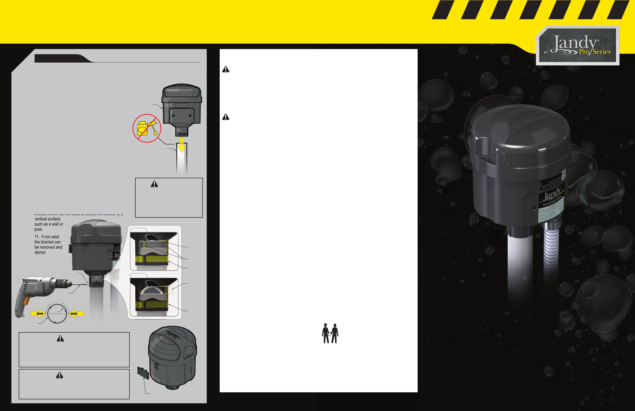
4. INSTALL BLOWER
Installation must be done in accordance with the National Electrical Code® (“NEC®”
or NFPA-70®) in the US, the Canadian Electrical Code (“CEC” or CSA C22.1) in
Canada, and/or any other local and national installation codes.
1. Refer to the “Select Blower” section (facing page) to ensure that you
have the correct blower size for your application.
2. Pressure tests to the system should be done prior to the installation
of the blower. See Warning Section on adjacent page.
3. Use 2" PVC pipe from the blower to jets or bubblers.
4. Slide Blower onto PVC Pipe. Lower until the stop
tabs make contact with the PVC pipe.
5. Blower should be installed vertically, away from
direct sunlight.
6. Do not glue or otherwise permanently attach the
blower to plumbing.
7. Do not remove the blower check valve diaphragm.
8. Drill two (2) 1/8" pilot holes through the textured fastener safe area
marked on the blower body. The holes should be drilled through the blower
body and PVC pipe. The holes should be oriented 180°
from one another.
9. Install one (1) 1/2” 8-18 thread forming screw into
each of the previously drilled pilot holes. The screws and
pipe should not interfere with the normal travel of the
check valve diaphragm.
10. The blower also comes equipped with a mounting
bracket which can be used to secure the blower to a
vertical surface
such as a wall or
post.
11. If not used
the bracket can
be removed and
stored.
bracket which can be used to secure the blower to a
vertical surface
such as a wall or
post.
11.
If not used
the bracket can
be removed and
stored.
Flat
Diaphragm
Travel
Distance
Flexed
Diaphragm
1/8" Bit
for Pilot Holes
Blower Body
PVC
Fastener
Safe Area
Fastener
Safe Area
Fastener
Safe Area
Stop Tabs
180°
2" PVC
Blower
Moutning Bracket
WARNING
Do not use chemical adhesives to
affi x the blower to the air inlet line.
Fumes from chemical adhesives
may accumulate in the piping and
explode causing property damage,
serious injury or death.
CAUTION
Blower must be affi xed to the plumbing using the fasteners
recommended in these instructions. Failure to do so may
allow the blower to come free of the plumbing during oper-
ation which could damage equipment and prevent proper
blower operation.
WARNING
Blower must be installed in an area well away from sourc-
es of exhaust such as gas pool and spa heater. Please
ensure that this blower is installed according to local codes
and Authority Having Jurisdiction (AHJ) requirements.
Product specificaties
| Merk: | JANDY |
| Categorie: | Niet gecategoriseerd |
| Model: | PSB110 |
Heb je hulp nodig?
Als je hulp nodig hebt met JANDY PSB110 stel dan hieronder een vraag en andere gebruikers zullen je antwoorden
Handleiding Niet gecategoriseerd JANDY

12 Mei 2026
16 September 2025
15 September 2025
21 Juli 2025
29 Maart 2025
28 Maart 2025
28 Maart 2025
28 Maart 2025
28 Maart 2025
28 Maart 2025
Handleiding Niet gecategoriseerd
Nieuwste handleidingen voor Niet gecategoriseerd
15 Juni 2026
15 Juni 2026
15 Juni 2026
15 Juni 2026
15 Juni 2026
15 Juni 2026
15 Juni 2026
15 Juni 2026
15 Juni 2026
15 Juni 2026