Jablotron CU-07 Handleiding


Lees hieronder de 📖 handleiding in het Nederlandse voor Jablotron CU-07 (3 pagina's) in de categorie Auto alarm. Deze handleiding was nuttig voor 21 personen en werd door 2 gebruikers gemiddeld met 4.5 sterren beoordeeld

Pagina 1/3
CU-07 Tracer unit 1/1 MKW51102
CU-07 TRACER unit
User manual and unit setting instructions
The CU-07 Tracer unit is a device which uses a GPS receiver to
detect the position of a car, a motorcycle or cargo and transmits it to
a web portal via a GSM network. The web portal allows further data
processing (online position monitoring, creation of a vehicle
logbook, etc.). The unit uses an integrated accelerometer which
detects movement and automatically controls the commencement
and termination of recorded journeys. Simply speaking, if the unit is
in motion, it records its geographical position and attempts to
transmit it to a collecting server in real time. If the attempt to send
the data fails, the unit saves it into its internal memory and sends it
later.
The unit indicates its status with an LED indicator.
Slow flashing Logging into the system or the GPS
signal has been lost
Rapid flashing The unit is waiting for dialing-in to
obtain its configuration (only the first
connection after purchasing)
SOS flashing (...---...) Unit failure
Permanently lit Motion indication, the journey is being
monitored
The LED is off Journey termination or
the unit’s power supply has been
disconnected
Journey commencement – the unit in idle state (a parked car)
and consumes minimum power as it waits for vehicle motion.
Once the vehicle starts moving (reaches a speed exceeding 3
km/h), the unit automatically switches into a mode in which it
transmits data concerning the changing position of the vehicle.
The commencement of a journey is signaled with a switched on
LED indicator which is then lit permanently for the whole
duration of the journey.
Journey termination – The journey recording is terminated
automatically. If the vehicle stops moving for a period of time
exceeding 30 seconds, the journey monitoring is paused and an
adjustable countdown towards its termination begins (200 sec –
85 min., the default setting is 5 min, see 2.6.). If the vehicle does
not start moving during the countdown, the journey is terminated
(the LED indicator goes off) and any further motion performed
after this period is considered a commencement of a new
journey. When waiting in a traffic jam, the current journey can be
terminated due to minimum vehicle motion in exceptional cases.
When further motion is detected, the unit commences a new
journey. You do not lose any data in such a case. The journey is
just split into several consecutive parts. NOTE: If the unit is
connected into a switchable socket in the car, then the journey
in progress is terminated every time the power supply is
switched off (usually when the ignition key is switched off).
1. Unit installation, connection and
configuration
1.1. Unit installation and connection
The unit can be connected to a 12 – 24 V voltage via a cigarette
lighter socket (e.g. in order to test its function and to find a
suitable place for installation). However, for standard
operation we recommend connecting the unit to the vehicle
power supply in a way which ensures that the voltage will not
be switched off – i.e. permanent connection to a car power
supply or at least into a socket with a permanent power supply.
If the unit is connected into a switchable socket, it commences
the journey with a certain delay as it has to detect the satellite
positions and reestablish the GSM connection when the power
supply is switched back on. The commencement of the journey
can then be projected as a straight line from the starting point
(or better the last target point) to the place where the unit
detects a correct GPS signal for the first time. The distance can
range from tens to hundreds of meters.
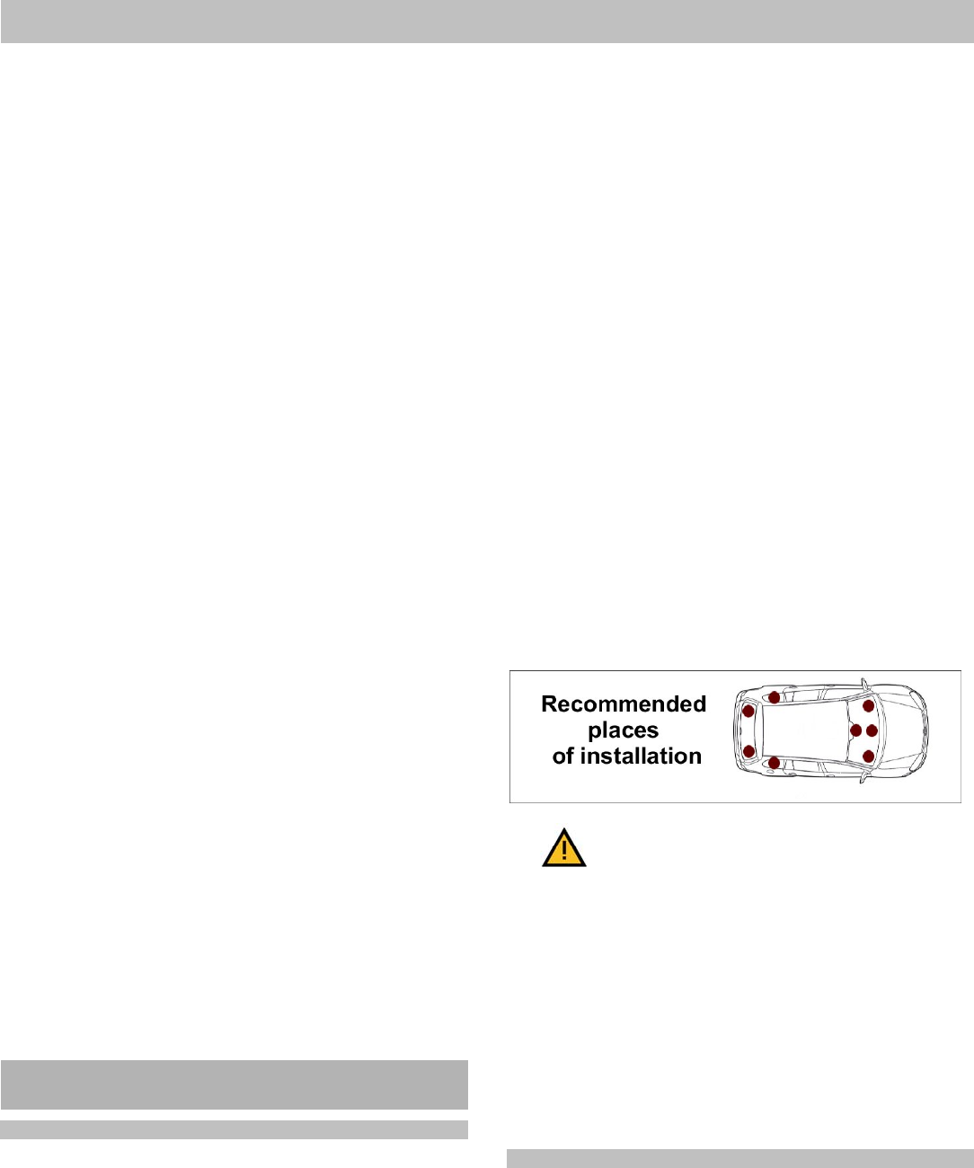
The unit itself should be installed in the vehicle at least 30
cm from the expected position of the driver or the
passengers. It is also advisable to install the unit near the
windows and in a horizontal position with the side marked
DOWN facing the ground. The unit must not be installed on
or near metal parts!!! The device contains a GPS antenna
whose correct positioning can increase the accuracy and speed
with which the position of the vehicle is detected. The unit can
for example be installed under the plastic parts of the
dashboard, in the upper section of the boot, etc. Generally
speaking, the better direct view of the sky and the horizon the
unit has, the better it will project your journeys. Beware of metal-
coated windscreens or possible metal dashboards (of older
lorries). GPS signal reception is reduced significantly under
them. In such a case the unit should be stuck to a rear view
mirror or in the back of the vehicle. The unit should not be
installed close to a radio receiver and loudspeakers in order to
avoid the unpleasant buzzing noise in the loudspeakers when
the unit is communicating (a similar effect to that caused by a
mobile phone).
When the unit is connected via a connector, it is necessary to
ensure that the connector cannot be ripped out of the socket
(the unit would not be able to record or transmit any information
about the journey). The unit can be fixed with a double-sided
self-adhesive tape included in the package. Wipe the place
properly before using the tape.
The following applies to an installation with a permanent
connection to the vehicle power supply:
GND – black wire
+U – red wire
We recommend having a fixed connection to the vehicle
power supply done by a professional company.
Although the device is protected with a fuse preventing its
internal circuits from possible damage, we still recommend
connecting its power supply via a 1A fuse which can prevent
against a possible short circuit and the resulting sending of the
unit to the manufacturer’s service station.
1.2. Primary configuration of the unit
When you have purchased the unit, you have to configure it
first. To do so, you will need your mobile phone and the
unit’s telephone number which you can find in the product
package. We recommend configuring the unit in a place where
you can receive GPS signals without any problems (i.e. in an
open space and not in a garage).
The primary configuration can be done by connecting a suitably
positioned unit (see 1.1) to the power supply. The unit’s system
LED starts flashing slowly after the connection to the voltage. All
If the unit is installed in an unsuitable
place, the manufacturer cannot
guarantee GPS signal reception!
CU-07 Tracer unit 2/2 MKW51102
parts of this unit are initialized during these approx. 2 minutes of
flashing. If the unit is connected to the power supply for the first
time after its purchase, the slow flashing changes to rapid
flashing after the two minutes, indicating that the unit is waiting
for configuration. When the unit has received its configuration
(from your tracer service provider) it sends a confirmatory SMS
reporting the successful setting to the number from which it was
configured. The unit is now ready for journey recording
Solving problems which might occur during primary
configuration:
I have not received a confirmatory SMS, even though the
whole process was carried out in conformity with the
instructions. Solution: try to repeat the process.
The unit’s LED indicator has started flashing SOS in Morse
code (3 dots, 3 dashes, 3 dots). Solution: a unit or SIM card
failure has been detected, contact the tracer service provider.
2. Advanced unit configuration
Advanced unit configuration increases the convenience
and functionality of the whole monitoring system. The
configuration can be carried out via SMS messages sent to
the unit’s telephone number.
Each SMS must begin with a six-digit number (the default
number is 123456). The manufacturer recommends
changing this password, see 2.1. The password should be
followed with a comma and then one or more commands
separated with other commas. The SMS must not exceed 160
characters.
2.1. Access password change
The manufacturer recommends changing the password. Be
careful when changing the password; if you forget it, it is
impossible to restart the unit to default settings. In such a
case contact the manufacturer.
Command format: Password,MCxxxxxxxxxxxx
where: xxxxxx is a new access password for the device
(the 6 characters should be repeated twice, only digits
can be entered)
Command example:
123456,MC654321654321 (the new password will be 654321)
2.2. Entering drivers’ telephone numbers
If the unit is installed in a vehicle which is used by multiple
drivers, it is possible to set the number of the driver who is going
to drive the vehicle easily by dialling into the unit from the
driver’s telephone. The device memory can hold telephone
numbers of up to 15 drivers who can identify themselves by
dialling into the unit. The telephone number can consist of 12
digits maximum and it must be entered in the international
format.
Command format: Password,TELx+yyyyyyyyyyyy
where: x – the unit’s reference number of the telephone
number (from 1 to 15);
yyyyyyyyyyyy – telephone number in international
format (max.12 digits excluding the «+» sign)
Example of a command programming numbers of drivers 1 and
2: 123456,TEL1+420608234567,TEL2+420777654321
Format of the command to erase a telephone number:
Password,TELx+0
Example of a command to erase driver 1’s telephone number:
123456,TEL1+0
Note: One SMS can contain multiple commands; the password
is only stated at the beginning of the SMS.
2.3. Driver selection by dialling in
A driver can assign himself to a journey by dialling into the unit
from his telephone if his number is recorded in the unit’s
memory (see 2.2). The unit terminates the call automatically and
the driver who has called into the unit is set for all the following
journeys until another driver dials in.
2.4. Driver selection by an SMS command
A driver can also be selected with an SMS command (e.g. a
function for a dispatcher). In order to change the current driver’s
number you have to enter the following command:
Command format: Password,Dxx
where: xx – the two-digit number of a driver (01 to 15)
Command example: 123456,D02 (to set driver 2)
2.5. Journey type setting
If you need to differentiate between various journey types
(private, business, etc.), you can set it before the
commencement of a journey by sending an SMS. The device
enables classification into five journey types. The current
journey type can be selected by sending an SMS command.
The journey type can be changed via an SMS command
without a password, but only from telephone numbers
recorded in the unit (see 2.2.). In such a case the driver’s
number changes automatically together with the journey type.
Command format: Tхх
where: хх – journey type:
00 = business (default)
01 = private
02 = service
03 = foreign business (e.g. due to the price of fuel)
03 = foreign personal (e.g. due to the price of fuel)
Command example: T01 (sets a private journey) and the driver
is changed according to the telephone number from which the
command was sent.
The journey type can also be changed using an SMS
command with a password. In such a case only the journey
type changes - the driver remains unchanged. This command
can also be sent from telephone numbers which are not
recorded in the given unit (function suitable e.g. for a
dispatcher).
Command format: Password,Tхх
where: хх – journey type (see above)
Command example: 123456,T01 (sets a private journey)
2.6. Journey termination timer setting
The device enables the setting of the time interval necessary for
journey termination. If we set the timer to 600 sec., then the unit
waits for vehicle motion detection for 10 minutes after the
journey termination. If the vehicle starts moving again, the
original journey continues. Otherwise the journey is terminated
and the unit switches to sleep mode.
Command format: Password,ETх
where х – number of seconds
permitted values: 200 s. - 5100 s. (85 min.)
default setting 300 s. (5 min.)
Command example: 123456,ET600 (time-out set for 10 min.)
2.7. SMS command reception confirmation
The device can confirm execution of the received SMS
commands based on the following parameter setting:
CU-07 Tracer unit 3/3 MKW51102
Command format: Password,REx
where: x – can have the following values:
0 – do not confirm any received SMS commands (default)
1 – confirm with an SMS message sent to the telephone number
from which the SMS command was received
Command example: 123456,RE1 (will be confirmed by
SMS the number from which the SMS command was received)
2.8. Ascertaining the current position
The current position of the unit can be ascertained by sending a
GPS command. The command requires a password. You will
receive an SMS message containing information about the
coordinates in degrees. If your mobile phone supports the direct
browsing of links in the received messages, the SMS also
includes a link to a website where you can directly view a map
showing the given position.
Command format: Password,GPS
Example of a command to ascertain the current position:
123456,GPS
2.9. Enabling SMS sending with activated roaming
The unit can confirm changes (e.g. choice of driver) by sending
an SMS. Confirmatory SMS message sending is forbidden
outside the national network. Enabling this function will result in
increased operating costs of your unit. The command can only
be set through your monitoring service provider.
2.10. Enabling data sending with activated roaming
The unit transmits data concerning the journey in progress to
the server using a GPRS connection. This is forbidden outside
the national GSM network. Enabling this function will result in
increased operating costs of your unit.
The command can only be set through your monitoring
service provider.
Note: If this function is not active, the data is saved in the unit
and it is then transferred to the server when the unit has
registered itself to the national GSM network again. You can
keep more than a month of daily journeys (approx. 15
hours/day) in the memory.
2.11. Notification of vehicle tampering and commencement
of a journey
The unit can notify you when your car is being tampered with
(e.g. shocks, towing away) by calling the telephone number from
which the SMS command was sent. The notification is
functional only if the unit is connected to a permanent
power supply. It becomes active when the journey
termination timeout has finished (see 2.6.) which is
indicated by switching off the LED indicator. You can speed
up the activation of this function by calling the unit’s
number and thus terminating the journey despite the
incomplete timeout.
Another option is a notification about the commencement of a
journey (speed exceeding 3 km/h) by calling the telephone
number from which the SMS command was sent. The
notification is functional only if the unit is connected to a
permanent power supply, and it only becomes active when
the journey termination timeout has finished (see 2.6.)
which is indicated by switching off the LED indicator. You
can speed up the activation of this function by calling the
unit’s number and thus terminating the journey despite the
incomplete timeout.
The above-mentioned “Notification“ functions are not security
functions and they cannot substitute a proper security system.
Command format: Password,Ax
where: x = 1 notification of vehicle tampering
x = 2 journey commencement notification
x = 0 notification disabled *(Note: see the note in
chapter 2.11. “Default settings“)
Command example: 123456,A1 (the unit calls the telephone
number from which the SMS command was send for approx. 15
seconds)
2.12. Default settings
Default settings of the unit’s settable parameters:
TELx the drivers’ telephone number list is empty
T journey type 00 (business)
D driver ID 01
ET journey time-out 300 s. (5 min.)
A dialling in (calling) 0 (disabled)
RE SMS confirmation 0 (disabled)
MC password set as 123456
* Note: when setting an SMS command concerning
confirmation by calling back (see 2.7.), it is necessary to
deactivate “voice mail“. Voice mail accepts calls
automatically even after the user’s call rejection which
results in increased operating costs for the unit's SIM card !
3. Technical specification
Power supply voltage 8 - 30 V
Maximum power consumption 200 mA /12 V
Nominal current in GPRS mode 120 mA /12 V
Standby consumption 15 mA /12 V
Dimensions 160 x 42 x 19 mm,
Weight 84 g
Operating temperature range -20 to +80°C
Comply with ETSI EN 301 511, ETSI EN 301 489-1,
EN 60950-1
Intended for connection to a 12V or 24V power supply. The unit
is intended for operation in road vehicles.
JABLOTRON ALARMS a.s. hereby declares that the CU-07 is in
compliance with the essential requirements and other relevant
provisions of Directive 1999/5/EC and ECE Regulation No.
10.03. The original of the conformity assessment can be found
at www.jablotron.com, Technical Support section .
Note: Although this product does not contain any harmful
materials we suggest you return the product to the dealer or
directly to the producer after use.
10R-03 5144
E
8


Product specificaties

Merk: Jablotron
Categorie: Auto alarm
Model: CU-07

Heb je hulp nodig?

Als je hulp nodig hebt met Jablotron CU-07 stel dan hieronder een vraag en andere gebruikers zullen je antwoorden