Intermatic IG2200-FMK Handleiding
Intermatic Niet gecategoriseerd IG2200-FMK
Bekijk gratis de handleiding van Intermatic IG2200-FMK (2 pagina’s), behorend tot de categorie Niet gecategoriseerd. Deze gids werd als nuttig beoordeeld door 18 mensen en kreeg gemiddeld 4.8 sterren uit 4 reviews. Heb je een vraag over Intermatic IG2200-FMK of wil je andere gebruikers van dit product iets vragen? Stel een vraag
Pagina 1/2
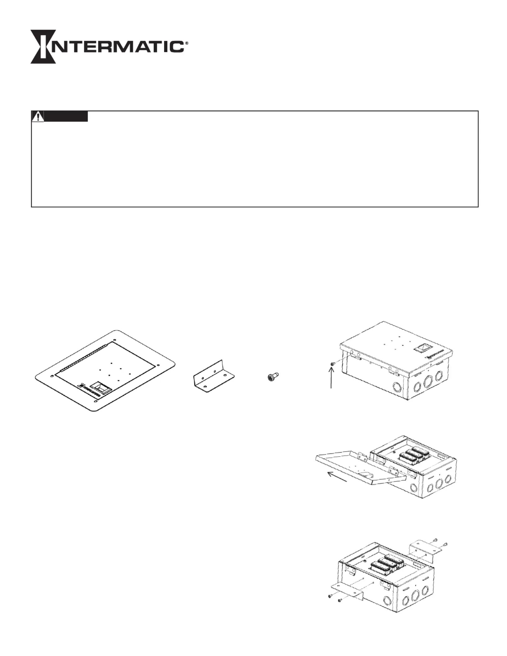
Included in kit:
(1) Flush Mount Cover
(2) Mounting
Brackets
(8) #8-32
Serrated
Self-Tapping
Screws
IMPORTANT SAFETY INSTRUCTIONS • SAVE THESE INSTRUCTIONS
INSTALLATION INSTRUCTIONS
IG2200-FMK
Flush Mount Kit
Risk of Fire or Electric Shock
• For indoor installations only.
• Only use hardware included with flush mount kit for installation.
• Follow all instructions included with surge protective device being used with flush mount kit.
• To be installed and or serviced by qualified personnel.
• Disconnect power at service panel or disconnect switch(es) before installing or servicing.
• Installation and wiring must be in accordance with national and local code requirements.
• KEEP DOOR CLOSED AT ALL TIMES when not servicing.
WARNING
APPLICATION NOTES
1. Thoroughly read instructions before installing flush mount kit.
2. Instructions should be retained for future reference.
3. For use with IG2240-IMS, IG2240-IM and IG2280-IM models. (Figures below show IG2240-IM model)
4. For use with ½” paneling material. (Drywall, panel board, etc.)
5. Observe warnings and instructions on front panel and unit label of flush mount plate and SPD unit.
Attach ush mount plate to surge protective device (SPD).
1) Remove cover retaining screw. (Fig. 1)
2) Remove SPD cover by sliding cover up and off SPD
housing. (Fig. 2)
3) Attach both mounting brackets using four #8-32
serrated self-tapping screws included with kit. (Fig. 3)
Figure 3
Figure 2
Figure 1
Retaining screw
Product specificaties
| Merk: | Intermatic |
| Categorie: | Niet gecategoriseerd |
| Model: | IG2200-FMK |
Heb je hulp nodig?
Als je hulp nodig hebt met Intermatic IG2200-FMK stel dan hieronder een vraag en andere gebruikers zullen je antwoorden
Handleiding Niet gecategoriseerd Intermatic

19 April 2026
18 April 2026
18 April 2026
17 April 2026
16 April 2026
16 April 2026
16 April 2026
14 April 2026
13 April 2026
16 November 2025
Handleiding Niet gecategoriseerd
Nieuwste handleidingen voor Niet gecategoriseerd
7 Juni 2026
7 Juni 2026
7 Juni 2026
7 Juni 2026
7 Juni 2026
6 Juni 2026
6 Juni 2026
6 Juni 2026
6 Juni 2026
6 Juni 2026