GE DSLVR48GHWW Handleiding
Bekijk gratis de handleiding van GE DSLVR48GHWW (8 pagina’s), behorend tot de categorie Wasdroger. Deze gids werd als nuttig beoordeeld door 46 mensen en kreeg gemiddeld 4.3 sterren uit 23.5 reviews. Heb je een vraag over GE DSLVR48GHWW of wil je andere gebruikers van dit product iets vragen? Stel een vraag
Pagina 1/8

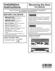
Installation
Instructions
Gas Dryer
or Visit our Web site at:
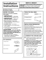
MATERIALS YOU WILL NEED
LEVEL
Step 1 Verify Your Gas Installation (see section 2).
Step 2 Prepare the Area and Exhaust for Installation of
New Dryer (see section 1).
Step 3 Check and Insure the Existing External Exhaust is
Clean (see section 1) and Meets Attached Installation
Specifications (see section 6).
Step 4 Remove the Foam Shipping Pads (see section 1).
Step 5 Move the Dryer to the Desired Location.
Step 6 Level Your Dryer (see section 8).
Step 7 Connect the Gas Supply (see section 3) and check
for leaks (see section 4).
Step 8 Connect the External Exhaust (see section 7).
Step 9 Connect the Power Supply (see section 5).
Step 10 Check the Operation of the Power Supply, Gas
Connections, and Venting.
Step 11 Place the Owners Manual and the Installation
Instructions in a Location Where They Will Be
Noticed By the Owner.
For Alcove or Closet Installation see section 9.
For Bathroom or Bedroom Installation see section 10.
For Mobile or Manufactured Home see section 11.
8" PIPE WRENCH
D
E
S
I
G
N
C
E
R
T
I
F
I
E
D
08
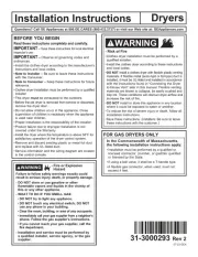
In the state of Massachusetts, installation must be performed by a qualified
or licensed contractor, plumber, or gasfitter qualified or licensed by the state.
WARNING RISK OF FIRE
• To reduce the risk of severe injury or death, follow all installation instructions.
• Clothes dryer installation must be performed by a qualified installer.
• Install the clothes dryer according to these instructions and in accordance with
local codes. In the absence of local codes, installation must comply with National
Fuel Gas Code, ANSIZ223.1/NFPA 54 or the Canadian Natural Gas and Propane
Installation Code, CSA B149.1.
• This dryer must be exhausted to the outdoors.
This act requires the governor of California to publish a list of substances known to the
state to cause cancer, birth defects or other reproductive harm and requires businesses to
warn customers of potential exposure to such substances. Gas appliances can cause minor
exposure to four of these substances, namely benzene, carbon monoxide, formaldehyde
and soot, caused primarily by the incomplete combustion of natural gas or LP fuels.
Properly adjusted dryers will minimize incomplete combustion. Exposure to these
substances can be minimized further by properly venting the dryer to the outdoors.
•
California Safe Drinking Water and Toxic Enforcement Act
•
Use only 4” rigid metal ducting for exhausting the clothes dryer to the outdoors.
• Do not install or store this appliance in any location where it could be exposed to
water and or weather.
• Save these instructions. (Installers: Be sure to leave these instructions with the
customer).
• DO NOT install a clothes dryer with flexible plastic ducting materials. If flexible
metal (semi-rigid or foil-type) duct is installed, it must be UL-listed and installed
in accordance with the instructions found in "Connecting The Dryer To House
Vent" on page 6 of this manual. Flexible ducting materials are known to collapse,
be easily crushed, and trap lint. These conditions will obstruct dryer airflow and
increase the risk of fire.
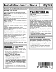
BEFORE YOU BEGIN
Read these instructions completely and
carefully.
•
IMPORTANT-
Save these
instructions for local inspector’s use.
•
IMPORTANT-
Observe
all governingcodes and ordinances.
• Note to Installer - Be sure to leave
these instructions with the customer.
• Note to Customer - Keep these
instructions with your Use and Care
Book for future reference.
• Before the old dryer is removed from
service or discarded, remove the dryer
door.
•
Service information and the wiring dia-
gram are located in the control console.
• Do not allow children on or in the
appliance. Close supervision of child-
ren is necessary when the appliance is
used near children.
•Install the dryer where the temp-
erature is above 50°F for satisfactory
operation of the dryer control system.
•Inspect the dryer exhaust outlet and
straighten the outlet walls if they are
bent.
EXHAUST HOOD
FLEXIBLE GAS LINE CONNECTOR
SOAP SOLUTION
FOR LEAK DETECTION
PIPE
COMPOUND
DUCT TAPE
GLOVES
SAFETY GLASSES
4" DIAM METAL ELBOW
10" ADJUSTABLE WRENCHES
(x2)
4" DUCT CLAMPS
OR
4" SPRING CLAMPS
(x2)
(x2)
TOOLS YOU
WILL NEED
SLIP JOINT PLIERS FLAT BLADE SCREWDRIVER
4" DIA. FLEXIBLE METAL (SEMI-RIGID)
UL LISTED TRANSITION DUCT
(IF NEEDED)
KIT WX08X10077 (INCLUDES 2 ELBOWS)
4" DIA. METAL DUCT
(RECOMMENDED)
4" DIA. FLEXIBLE METAL (FOIL TYPE)
UL LISTED TRANSITION DUCT
(IF NEEDED.)

Installation Instructions
1 PREPARING FOR INSTALLATION
OF NEW DRYER
Minimum Clearance Other Than Alcove or Closet Installation
Minimum clearance to combustible surfaces and for air opening are: 0 in. clearance both sides and 1 in. rear. Consideration
must be given to provide adequate clearance for proper operation and service.
2 GAS REQUIREMENTS
DISCONNECTING GAS
The use of old flexible connectors can cause leaks and
personal injury. Always use new flexible connectors when
installing gas appliances.
WAR NG - NEVER R SE OLDNI EU
FLEXIBLE NNECTORS.CO
2
TILT THE DRYER SIDEWAYS
AND REMOVE THE FOAM
SHIPPING PADS BY
PULLING AT THE SIDES
AND BREAKING THEM
AWAY FROM THE DRYER
LEGS. BE SURE TO
REMOVE ALL OF THE
FOAM PIECES AROUND
THE LEGS.
•
Installation must conform to local codes and ordinances,
or in their absence, the NATIONAL FUEL GAS CODE,
ANSI Z223.
•This gas dryer is equipped with a Valve & Burner Assem-
bly for use only with natural gas. Using conversion kit
WE2 5X0217, your local service organization can convert
this dryer for use with propane (LP) gas. ALL CONVER-
SIONS S T BE MADE BY PRO RLY TRA DMU PE INE
AND QUAL D RSO L AND IN ACCOR-IFIE PE NNE
DA E WITH LOCAL CODES AND ORDINANCENC
REQUIREMENTS.
•The dryer must be disconnected from the gas supply
piping system during any pressure testing of that system
at a test pressure in excess of 0.5 PSI (3.4 KPa).
•The dryer must be isolated from the gas supply piping
system by closing the equipment shut-off valve during
any pressure testing of the gas supply piping of test
pressure equal to or less than 0.5 PSI (3.4 KPa).
WARNING
DRYER GAS SUPPLY CONNECTION
2"
2-5/8" 3/8" NPT MALE THREAD GAS SUPPLY
NOTE: Add to vertical dimension
the distance between cabinet
bottom to floor.
GAS SUPPLY
•A 1/8-in.National Pipe Taper thread plugged tapping,
accessible for test gauge connection, must be installed
immediately upstream of the gas supply connection to
the dryer. Contact your local gas utility should you have
questions on the installation of the plugged tapping.
Supply line is to be 1
•Yo muu st use hwit t ish dr rye a fl iex bl mee tal co rnnecto
/2-in. rigid pipe and equipped with
an accessible shut-off within 6 ft. of, and in the same
room with the dryer.
•
•
Use pipe thread sealer compound or Teflon tape
appropriate for natural or LP gas.
li tes d co tnnec or ANSI 1.2Z2 4 / .10 C 6SA . The length of
the connect shall not exceed 3 ft.
•
•
Connect flexible metal connector to dryer and gas supply.
Open shut-off valve.
TIP: Install your dryer before installing your washer.
This will allow better access when installing dryer exhaust.
REMOVING LINT FROM WALL
EXHAUST OPENING
INTERNAL DUCT
OPENING CHECK THAT EXHAUST
HOOD DAMPER OPENS
AND CLOSES FREELY.
WALL
Remove and discard existing plastic or metal foil
transition duct and replace with UL listed transition
duct.
•
DISCONNECT AND DISCARD OLD
FLEXIBLE GAS CONNECTOR AND
OLD TRANSITION DUCTING
MATERIAL. REPLACE WITH NEW
CSA(AGA) APPROVED FLEXIBLE
GAS LINE CONNECTOR AND UL
APPROVED TRANSITION DUCT.
TURN GAS
SHUT-OFF VALVE
TO THE OFF
POSITION.

3
4 LEAK TEST
Installation Instructions
FLARE NPT
PIPE SIZE
Listed connector ANSI Z21.24 / CSA 6.10
Caution: Use adapt rs as show . Connector nuts must not e n
be connected directly to pipe threads.
Note: The connector and ttings are designed for use only
on the original installation and are not to be reused for
another appliance or at another location. Keep are end of
adaptor free of grease, oil and thread sealant.
1/8" NPT PIPE
PLUG FOR
CHECKING GAS
INLET PRESSURE
PIPE SIZE
AT LEAST 1/2"
3/8" NPT
TIGHTEN ALL CONNECTIONS
USING TWO ADJUSTABLE WRENCHES.
DO NOT OVERTORQUE GAS CONNECTIONS!
TIGHTEN THE FLEXIBLE
GAS LINE USING TWO
ADJUSTABLE WRENCHES.
Product specificaties
| Merk: | GE |
| Categorie: | Wasdroger |
| Model: | DSLVR48GHWW |
Heb je hulp nodig?
Als je hulp nodig hebt met GE DSLVR48GHWW stel dan hieronder een vraag en andere gebruikers zullen je antwoorden
Handleiding Wasdroger GE

10 Augustus 2025
10 Augustus 2025
10 Augustus 2025
8 Juli 2025

6 Mei 2025
6 Mei 2025

1 Maart 2025
20 Februari 2025
30 Januari 2025

30 Januari 2025
Handleiding Wasdroger
- Mio Star
- Delonghi
- Kunft
- Khind
- Classique
- PKM
- Avanti
- Sharp
- Toshiba
- Elba
- New Pol
- Zerowatt
- Fagor
- Kinujo
- Teka
Nieuwste handleidingen voor Wasdroger
2 September 2025
2 September 2025
2 September 2025
2 September 2025
2 September 2025
1 September 2025
1 September 2025

1 September 2025
1 September 2025
1 September 2025