Festo VMPAL-EPL-IPO32 Handleiding
Festo Niet gecategoriseerd VMPAL-EPL-IPO32
Bekijk gratis de handleiding van Festo VMPAL-EPL-IPO32 (32 pagina’s), behorend tot de categorie Niet gecategoriseerd. Deze gids werd als nuttig beoordeeld door 14 mensen en kreeg gemiddeld 5.0 sterren uit 2 reviews. Heb je een vraag over Festo VMPAL-EPL-IPO32 of wil je andere gebruikers van dit product iets vragen? Stel een vraag
Pagina 1/32
Translation of the original instructions
© 2020 all rights reserved to Festo SE & Co. KG
IO-Link
®
, TORX
®
are registered trademarks of the respective trademark owners in
certain countries.
1About this document
This document describes the IO-Link/I-Port interface of the valve terminal.
1.1Applicable Documents
All available documents for the product www.festo.com/sp.è
DocumentsProductContents
DescriptionValve terminal MPAL-VIAssembly, Installation, Operating
InstructionsValve terminal MPAAssembly
Multiple documentationBus node CTEU-...Assembly, Installation, Operating
Tab. 1 Applicable Documents
2Safety
2.1General Safety Instructions
–Prior to mounting, installation and maintenance work: Switch off power sup-
ply and secure it from being switched back on.
–Prior to mounting, installation and maintenance work: Switch off compressed
air supply and secure it from being switched back on.
–Exhaust system parts with stored compressed air.
–This product can generate high frequency malfunctions, which may make it
necessary to implement interference suppression measures in residential
areas.
–For the electrical power supply with extra-low voltages, use only PELV circuits
that guarantee a reliable separation from the mains network.
–Observe IEC60204-1/EN60204-1.
–Comply with the handling specifications for electrostatically sensitive devices.
–Only use the product if it is in perfect technical condition.
–Only use the product in original status without unauthorised modifications.
–Use exclusively in combination with modules and components that are certi-
fied for the specific product variant and have been tested and approved by
Festo.
2.2Intended Use
The product is used to control pneumatic actuators and for installation in
machines and automated systems.
2.3Training of Qualified Personnel
Work on the product should only be conducted by qualified personnel.The spe-
cialized personnel must be familiar with the installation and operation of electrical
and pneumatic control systems.
3Additional Information
–Accessories www.festo.com/catalogueè
–Spare parts www.festo.com/sparepartsè
4Service
Contact your regional Festo contact person if you have technical questions
èwww.festo.com.
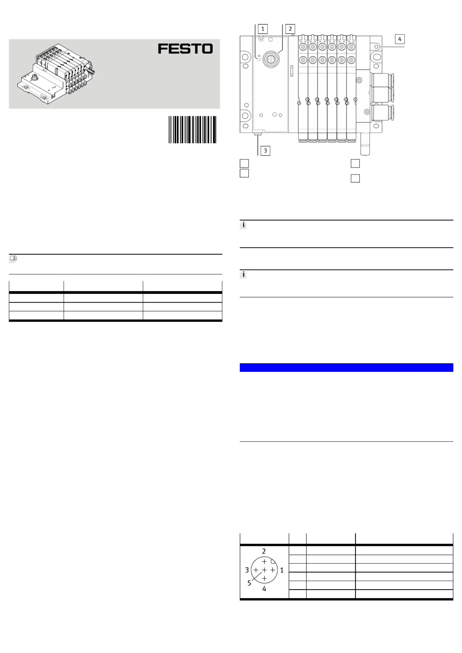
5Product Design
1
Status LED X1
2
IO-Link/I-Port interface
3
Earthing screw for connection to
functional earth ( TORX, T20)
4
Earth terminal (optional) for con-
nection to functional earth
Fig. 1 Display and connecting elements
6Assembly
Details on mounting are described in the description of the MPAL-VI valve termin-
al 1.1 Applicable Documents.è
7Pneumatic Installation
Details on the pneumatic installation are described in the description of the
MPAL-VI valve terminal 1.1 Applicable Documents.è
8Electrical Installation
8.1Power Supply
The operating voltage is supplied via the IO-Link master or the CTEU bus node.
The load voltage is supplied via the IO-Link master port class B or the CTEU bus
node. When using a IO-Link master port class A, the load voltage supply must be
supplied separately. Separate fuses are required for operating and load voltage.
8.2Earthing the Valve Terminal
NOTICE!
Observe the following points to avoid malfunctions as a result of electromagnetic
interference:
•Use a large-cross-section earth conductor that is as short as possible. The
earth conductor should ideally be a braided conductor, alternatively a cable
with a cross section of at least 2.5mm
2
, preferably 4mm
2
, and a maximum
length of 20cm. A different cable may be required depending on the installa-
tion situation.
•Connect the earth terminal with low resistance and low impedance to the
earth potential.
–Connect one of the earth terminals to the earth potential 5 Product Design.è
8.3IO-LinkI-port interface
Through the IO-Link/I-Port interface , the valve terminal can be connected as fol-
lows:
–Directly to the fieldbus, through mounting of a CTEU bus node on the valve
terminal
–Decentralised to an external IO-Link master
–Decentralised at an external I-Port master (e.g. CTEU)
Electrical connection:
–Plug connector, 5-pin, M12x1, A-coded
Port Pin Allocation IO-Link/I-Port Interface
ConnectionPinAllocationFunction
124 V
EL/SEN
(PS)Operating voltage supply
224 V
VAL / OUT
(PL)Load voltage supply
30 V
EL/SEN
(PS)Operating voltage supply
4C/QData communication
50 V
VAL / OUT
(PL)Load voltage supply
Housing, FEFunctional earth (optional)
Tab. 2 Port Pin Allocation IO-Link/I-Port Interface
Device Description File IODD
If the valve terminal is operated as a IO-Link device, download the corresponding
device description file: www.festo.com/sp.è
8117297
VMPAL-EPL-IPO32
End Plate for MPAL-VI
8117297
2019-11b
[8117299]
Instructions| Assembly, Installation
Festo SE & Co. KG
Ruiter Straße 82
73734 Esslingen
Germany
+49 711 347-0
www.festo.com
Product specificaties
| Merk: | Festo |
| Categorie: | Niet gecategoriseerd |
| Model: | VMPAL-EPL-IPO32 |
Heb je hulp nodig?
Als je hulp nodig hebt met Festo VMPAL-EPL-IPO32 stel dan hieronder een vraag en andere gebruikers zullen je antwoorden
Handleiding Niet gecategoriseerd Festo

3 Mei 2026
30 April 2026
29 April 2026
29 April 2026
29 April 2026
29 April 2026
28 April 2026
28 April 2026
28 April 2026
28 April 2026
Handleiding Niet gecategoriseerd
Nieuwste handleidingen voor Niet gecategoriseerd
23 Juli 2026
23 Juli 2026
23 Juli 2026
23 Juli 2026
23 Juli 2026
23 Juli 2026
23 Juli 2026
23 Juli 2026
23 Juli 2026
22 Juli 2026