Festo VACC-S13-18-K4-3U-NM4ME Handleiding
Festo Niet gecategoriseerd VACC-S13-18-K4-3U-NM4ME
Bekijk gratis de handleiding van Festo VACC-S13-18-K4-3U-NM4ME (2 pagina’s), behorend tot de categorie Niet gecategoriseerd. Deze gids werd als nuttig beoordeeld door 54 mensen en kreeg gemiddeld 4.0 sterren uit 2 reviews. Heb je een vraag over Festo VACC-S13-18-K4-3U-NM4ME of wil je andere gebruikers van dit product iets vragen? Stel een vraag
Pagina 1/2
VACC-S13-18-K4-...-NM4ME
Solenoid coil
Festo SE & Co. KG
Ruiter Straße 82
73734 Esslingen
Deutschland
+49 711 347-0
www.festo.com
Operating instructions
8168859
2021-11a
[8168861]
Translation of the original instructions
© 2022 all rights reserved to Festo SE & Co. KG
1
Identification EX
Identification markCertificate
Ex eb mb IIC T6, T5, T4 GbDNV 17.0042X
Ex tb IIIC T85°C, T95°C, T130°C Db
Tab. 1
2
Certified Products
VoltageType
24 V DC/ACVACC-S13-18-K4-1UF-…ME
24 V DC/ACVACC-S13-18-K4-1U-…ME
110 V DC/ACVACC-S13-18-K4-2U-…ME
230 V DC/ACVACC-S13-18-K4-3U-…ME
60 V DC/ACVACC-S13-18-K4-27U-…ME
Tab. 2
3Applicable Documents
NOTICE
Technical data for the product can have different values in other documents. For
operation in an explosive atmosphere, the technical data in this document always
have priority.
All available documents for the product
è
www.festo.com/sp.
4Safety
4.1General safety instructions
–
The solenoid coils can be used in combination with the specified solenoid
valves in zones 1 and 2 for potentially explosive gas atmospheres and in zones
21 and 22 for potentially explosive dust atmospheres.
–Operate the solenoid valve with compressed air only.
–
The device is not intended for use with other fluids.
–Observe the specifications on the product labelling.
–
Do not commission the solenoid coil until after assembly.
–Observe the operating conditions.
–Extraction of the operating medium outside the potentially explosive area.
–
Installation and commissioning should only be carried out by qualified elec-
trical specialists.
4.2Intended use
The solenoid coil is intended to be used to actuate valves from Festo.
4.3Identification X: special conditions
VACC-S13-18-K4-1UF-...ME
–Solenoid coil includes an internal protective device.
–
Only use specified solenoid valves.
–The range of application is dependent on the ambient temperature.
–
Observe the permitted mounting position of the solenoid coil
è
10 Technical
data.
–
Protect the device from electrostatic discharge.
VACC-S13-18-K4-...U-...ME
–
Only operate solenoid coils with fuses connected in series
è
10 Technical data.
–The interruption rating of the fuses must be equal to or greater than 1500 A.
–
Only use specified solenoid valves.
–
The range of application is dependent on the ambient temperature.
–
Observe the permitted mounting position of the solenoid coil
è
10 Technical
data.
–Protect the device from electrostatic discharge.
5Function
When switching on the voltage, the solenoid is energised, and the valve is actu-
ated. A built-in bridge rectifier limits the switch-off overvoltage.
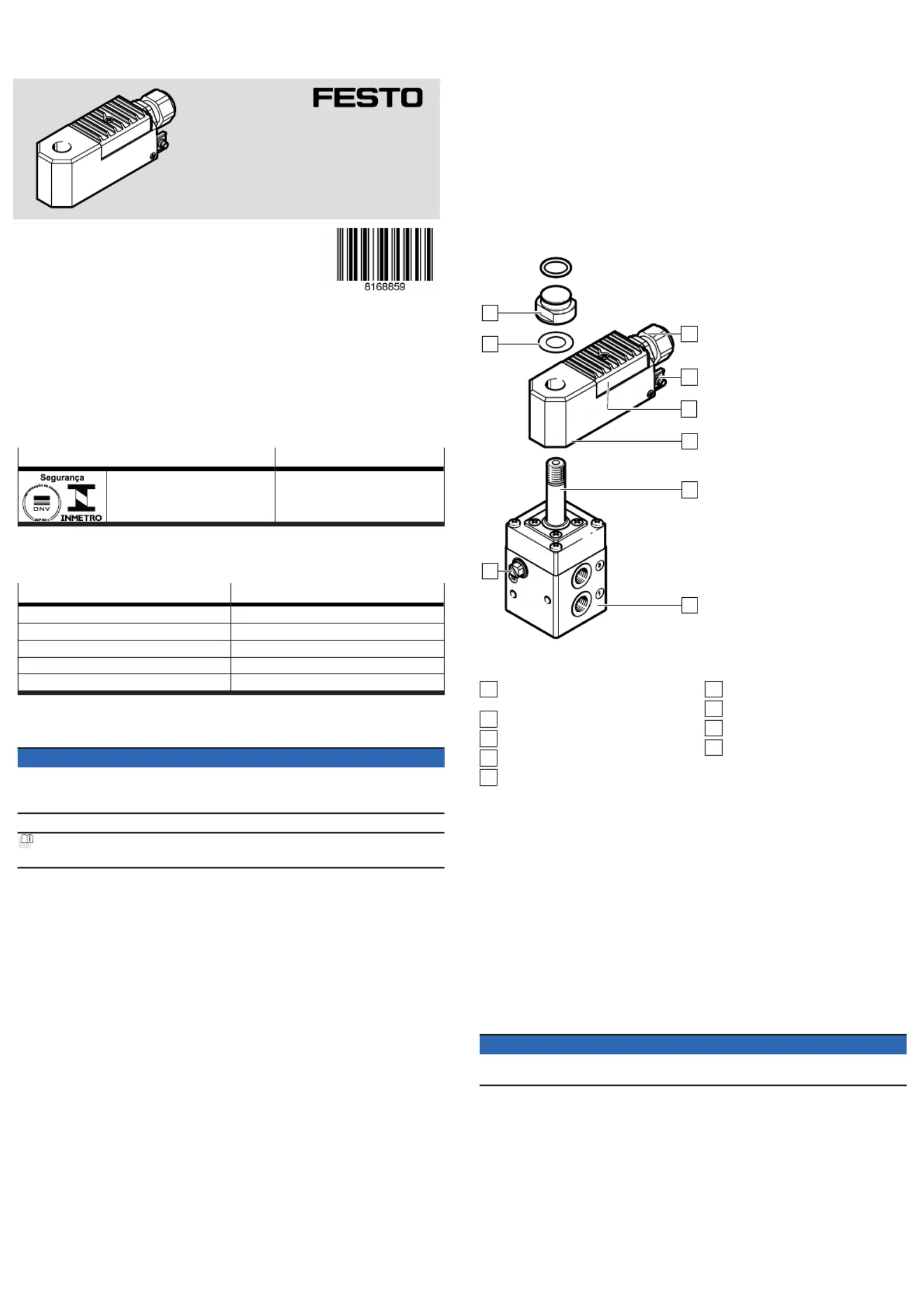
6
Assembly
1
2
3
4
5
6
7
8
9
Fig.1
1
Port 12 (only for external pilot air
supply)
2
Spring washer
3
Vent screw/retaining nut
4
Cable connector (with cap nut)
5
Protective earth connection
6
Cover, terminal housing
7
Solenoid coil
8
Armature guide tube
9
Solenoid valve
6.1Mechanical
When loosening the cap nut, prevent the cable connector from working loose.
Note tightening torque: cable fitting 2.3 Nm; cap nut 1.5 Nm.
1.Push the solenoid coil and spring washer over the armature guide tube.
–Sealing compound points to the solenoid valve.
2.Tighten vent screw. Twisting the solenoid coil is no longer possible (tightening
torque 4 … 6 Nm).
3.
Release terminal housing cover.
4.Connect electrical cables to the terminals. Note polarity (tightening torque
2 … 3 Nm).
5.Connect the solenoid coil to the equipotential bonding by the inner or outer
protective earth connection.
6.Close terminal housing cover (tightening torque 0.6 … 0.7 Nm).
7.With external pilot air supply, use connection 12.
8.Seal unused openings with blanking plugs or slot covers.
NOTICE
The surface coating of the solenoid valves is electrically non-conductive.
•Include the device in the system equipotential bonding.
6.2Pneumatic
1.
Mount connecting cables and fittings properly. Before commissioning, remove
residues, such as chips, rust and water.
2.Switch off pressure to the compressed air lines.
3.Use only fittings with cylindrical threaded lugs and sealing rings or cutting
rings.
4.
Do not use PTFE or hemp fibres on the threads.
5.Insert all sealing rings supplied with the NAMUR mounting kit between sole-
noid valve and drive or mounting plate.
6.If port 1 with control signal 2 bar, then supply auxiliary energy 2 bar to<>
port 12.
7.
Do not use anti-friction coating or lubricant.
Product specificaties
| Merk: | Festo |
| Categorie: | Niet gecategoriseerd |
| Model: | VACC-S13-18-K4-3U-NM4ME |
Heb je hulp nodig?
Als je hulp nodig hebt met Festo VACC-S13-18-K4-3U-NM4ME stel dan hieronder een vraag en andere gebruikers zullen je antwoorden
Handleiding Niet gecategoriseerd Festo

3 Mei 2026
30 April 2026
29 April 2026
29 April 2026
29 April 2026
29 April 2026
28 April 2026
28 April 2026
28 April 2026
28 April 2026
Handleiding Niet gecategoriseerd
Nieuwste handleidingen voor Niet gecategoriseerd
23 Juli 2026
23 Juli 2026
23 Juli 2026
23 Juli 2026
23 Juli 2026
23 Juli 2026
22 Juli 2026
22 Juli 2026
22 Juli 2026
22 Juli 2026