Ferm BLM1001 Handleiding
Ferm Niet gecategoriseerd BLM1001
Bekijk gratis de handleiding van Ferm BLM1001 (26 pagina’s), behorend tot de categorie Niet gecategoriseerd. Deze gids werd als nuttig beoordeeld door 67 mensen en kreeg gemiddeld 4.5 sterren uit 4 reviews. Heb je een vraag over Ferm BLM1001 of wil je andere gebruikers van dit product iets vragen? Stel een vraag
Pagina 1/26
Ferm B.V. • P.O. Box 134 • 8280 AC Genemuiden NL • Web: www.ferm.com0107/18
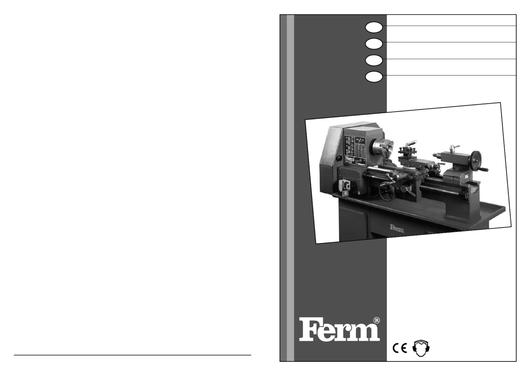
USERS MANUAL
Metal turning lathe02
BEDIENUNGSANLEITUNG
Metalldrehmaschine11
GEBRUIKSAANWIJZING
Metaaldraaibank21
MODE D’EMPLOI
Tour à métaux31
BRUKSANVISNING
Vinkelslipmaskin 20
KÄYTTÖOHJE
Kulmahiomakone 24
BRUKSANVISNING
Vinkelsliper 29
BRUGER VEJLEDNING
Vinkelslibere 33
Art.nr: 330950
Art.nr. 330960GB
D
NL
F
MD-350/MD-500
Product specificaties
| Merk: | Ferm |
| Categorie: | Niet gecategoriseerd |
| Model: | BLM1001 |
Heb je hulp nodig?
Als je hulp nodig hebt met Ferm BLM1001 stel dan hieronder een vraag en andere gebruikers zullen je antwoorden
Handleiding Niet gecategoriseerd Ferm

16 Juni 2023
1 Juni 2023
31 Mei 2023
29 Mei 2023
21 Mei 2023
13 Mei 2023
11 Mei 2023
10 Mei 2023
6 Mei 2023
3 Mei 2023
Handleiding Niet gecategoriseerd
Nieuwste handleidingen voor Niet gecategoriseerd
23 Juli 2026
23 Juli 2026
23 Juli 2026
22 Juli 2026
22 Juli 2026
22 Juli 2026
22 Juli 2026
22 Juli 2026
22 Juli 2026
21 Juli 2026