Epcom X3435A Handleiding
Epcom Niet gecategoriseerd X3435A
Bekijk gratis de handleiding van Epcom X3435A (4 pagina’s), behorend tot de categorie Niet gecategoriseerd. Deze gids werd als nuttig beoordeeld door 13 mensen en kreeg gemiddeld 4.4 sterren uit 8 reviews. Heb je een vraag over Epcom X3435A of wil je andere gebruikers van dit product iets vragen? Stel een vraag
Pagina 1/4
Page 1 of 4
Installation and Operation Instructions
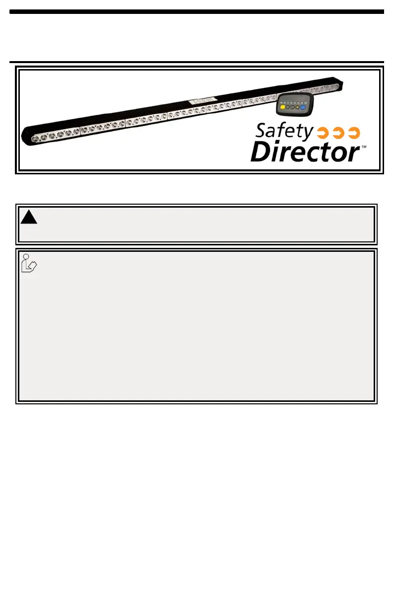
The LED Safety Director™ is a compact high-intensity warning system designed to direct trafc approaching from the rear of a stationary vehicle. The compact light-
stick design allows for unobtrusive interior or exterior mounting, either ush to the vehicle or using the provided mounting brackets. Inside the cab a modern, soft touch
controller provides ngertip control of the Safety Director's eight built-in ash patterns and features an LED display that mimics the selected pattern in real time.
1. Proper installation combined with operator training in the use, care, and maintenance of emergency warning devices are essential to ensure
the safety of you and those you are seeking to protect.
2. Exercise caution when working with live electrical connections.
3. This product must be properly grounded. Inadequate grounding and/or shorting of electrical connections can cause high current arcing,
which can cause personal injury and/or severe vehicle damage, including re.
4. Proper placement and installation are vital to the performance of this warning device. Install this product so that output performance of the
system is maximized and the controls are placed within convenient reach of the operator so that s/he can operate the system without losing
eye contact with the roadway.
5. Do not install this product or route any wires in the deployment area of an air bag. Equipment mounted or located in an air bag deployment
area may reduce the effectiveness of the air bag or become a projectile that could cause serious personal injury or death. Refer to the
vehicle owner’s manual for the air bag deployment area. It is the responsibility of the user/operator to determine a suitable mounting location
ensuring the safety of all passengers inside the vehicle particularly avoiding areas of potential head impact.
6. It is the responsibility of the vehicle operator to ensure during use that all features of this product work correctly. In use, the vehicle operator
should ensure the projection of the warning signal is not blocked by vehicle components (i.e., open trunks or compartment doors), people,
vehicles or other obstructions.
7. The use of this or any other warning device does not ensure all drivers can or will observe or react to a warning signal. Never take the right-
of-way for granted. It is your responsibility to be sure you can proceed safely before entering an intersection, driving against trafc, respond-
ing at a high rate of speed, or walking on or around trafc lanes.
8. This equipment is intended for use by authorized personnel only. The user is responsible for understanding and obeying all laws regarding
warning signal devices. Therefore, the user should check all applicable city, state, and federal laws and regulations. The manufacturer as-
sumes no liability for any loss resulting from the use of this warning device.
Do not install and/or operate this safety product unless you have read and understand the safety information
contained
Failure to install or use this product according to manufacturer’s recommendations may result in property damage, serious injury, and/or death to
those you are seeking to protect!
!
WARNING!
Specications:
Size: Light stick: 48” x 4 1/2” x 2”
Control box: 6” x 3 3/4” x 3/4”
Weight: Light stick: 6 lb.
Control box: 0.5 lb.
Current draw (12 VDC system): 3A MAX.
Wire the Safety Director:
Wire the safety directorinto the vehicles's 12V system according to Figure 2.
Provide a 5A fuse near the power take off. Use 16AWG wire or larger for the Red
and Black wire connections. If the Auxiliary Output is not used, cap the orange wire
from the Control Box. Route the lightbar cable from the Stick to the Control Box and
plug them together.
Unpacking:
Carefully remove the unit and place it on a at surface. Examine
the unit for transit damage, etc. If the vehicle has an electrical
system other than 12 Volts DC negative ground, contact your local
representative or call the manufacturer for instructions.
Installation & Mounting:
The SAFETY DIRECTOR was designed with a exible mounting system which allows
it to be mounted almost anywhere. For questions concerning a specic application
call customer service.
Prior to mounting, consideration should be given to cable location. The cable should
exit the endcap on the left side of the SAFETY DIRECTOR as you face the front of
the lightbar. Reversed mounting will result in all of the ash patterns being reversed.
The mounting location should be chosen such that there is maximum visibility to the
oncoming trafc.
Product specificaties
| Merk: | Epcom |
| Categorie: | Niet gecategoriseerd |
| Model: | X3435A |
| Kleur van het product: | Zwart |
| Breedte: | 1219.2 mm |
| Aantal lampen: | 48 lampen |
| Soort lamp: | LED |
| Stroom: | 1.6 A |
| Type stroombron: | DC |
| DC voltage input: | 12 V |
| Certificering: | SAE J595 Class I, CE, R10 |
| Aantal leds: | 48 |
| Type product: | Lichtbalk |
| Aantal lichteffecten: | 9 |
Heb je hulp nodig?
Als je hulp nodig hebt met Epcom X3435A stel dan hieronder een vraag en andere gebruikers zullen je antwoorden
Handleiding Niet gecategoriseerd Epcom

6 Januari 2024
6 Januari 2024
6 Januari 2024
6 Januari 2024
6 Januari 2024
6 Januari 2024
6 Januari 2024
6 Januari 2024
6 Januari 2024
6 Januari 2024
Handleiding Niet gecategoriseerd
Nieuwste handleidingen voor Niet gecategoriseerd
8 Juni 2026
8 Juni 2026
8 Juni 2026
8 Juni 2026
8 Juni 2026
8 Juni 2026
8 Juni 2026
8 Juni 2026
8 Juni 2026
8 Juni 2026