Enermax ETS-T50 AXE ARGB Handleiding
Enermax Ventilator ETS-T50 AXE ARGB
Bekijk gratis de handleiding van Enermax ETS-T50 AXE ARGB (2 pagina’s), behorend tot de categorie Ventilator. Deze gids werd als nuttig beoordeeld door 84 mensen en kreeg gemiddeld 4.1 sterren uit 8 reviews. Heb je een vraag over Enermax ETS-T50 AXE ARGB of wil je andere gebruikers van dit product iets vragen? Stel een vraag
Pagina 1/2
*Intel LGA775/115X/1366
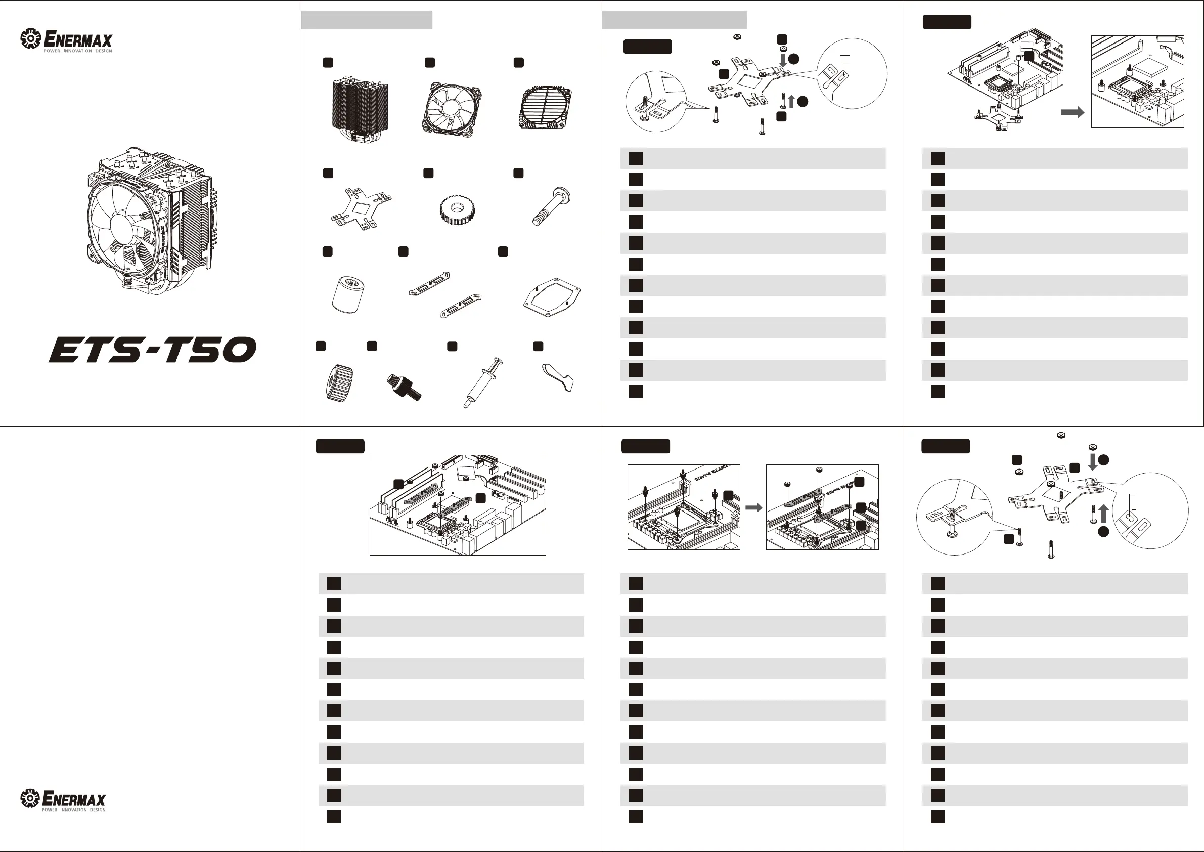
Step 1.1
Step 1.2
*Intel LGA775/115X/1366 installation
Step 1.3
*Intel LGA775/115X/1366 installation
Step 2
*Intel LGA 2011/ 2066
installation
Step 3.1
*AMD installation
A
CPU Cooler
C
Air Guide
D
D
D
E
E
E
F
F
F
G
Stand-off
H
H
Intel Mounting PlateAMD Mounting Plate
I
Back PlateWasherPosition Screw
J
J
K
K
Intel LGA
2011/2066
Screw
Nut
L
Thermal Grease
B
Fan
M
Spreader
LGA1366
LGA115X
LGA775
©2019 ENERMAX TECHNOLOGY CORPORATION. All right reserved. Specifications are subject
to change without prior notice. Some trademarks may be claimed as the property of others.
User’s Manual
ARGB VERSION
Chapter 1Part ListChapter 2Installaon
EN
DE
FR
IT
PL
ES
RU
TW
CN
KR
JP
ID
EN
DE
FR
IT
PL
ES
RU
TW
CN
KR
JP
ID
EN
DE
FR
IT
PL
ES
RU
TW
CN
KR
JP
ID
EN
DE
FR
IT
PL
ES
RU
TW
CN
KR
JP
ID
EN
DE
FR
IT
PL
ES
RU
TW
CN
KR
JP
ID
Insert the position screws into the proper holes on the back plate. Then use the washers to fix
the position screws. 《 If your CPU platform is Intel LGA2011 / 2066, please skip to step 2》
Drehen Sie die Montageschrauben in die zu Ihrem Sockel passende Bohrung in der
Backplate wie abgebildet an. 《Wenn Sie einen LGA2011 / 2011-3 / 2066 -Sockel verwenden,
gehen Sie bitte zu Schritt 2 über 》
Insérez les vis de position dans les trous correspondant à votre socket du CPU sur la plaque
arrière. Puis fixez-les avec les rondelles. 《 S’il s’agit d’un processeur Intel LGA2011 / 2066,
passez à l'étape 2 》
Inserire le viti di montaggio nel foro appropriato nella piastra posteriore come mostrato nella
figura sotto. 《 Se la piattaforma CPU è Intel LGA2011 / 2066, si prega di passare al punto 2 》
Włóż śruby pozycjonujące do odpowiednich otworów na płycie tylnej. Następnie użyj podkładek
w celu zamocowania śrub pozycjonujących.《Platformy Intel LGA2011 / 2066: Proszę przejść
do punktu 2 》
Inserte los tornillos de montaje en el agujero correspondiente en la placa trasera como se ve
en la imagen abajo. 《 Si su plataforma de CPU es Intel LGA2011 / 2066, por favor vaya
directamente al paso 2》
Установите винты для крепежной пластины в соответствующие отверстия для вашего процессора.
Установите промежуточные стойки на винты.
《Если ваша CPU платформа является Intel LGA2011 /
2011-3 / 2066, пожалуйста, перейдите к шагу номер 2 》
在背板上依系統CPU腳位所標示的孔位插入定位螺絲並套上墊圈固定。《如果您的主機板是
Intel LGA2011 / 2066,請直接跳至步驟2。》
在背板上根据系统CPU脚位所标示的孔位插入定位螺丝并套上垫圈固定。《如果您的主板是Intel
LGA2011 / 2066,请直接跳至步骤2》
브라켓 구멍에 알맞은 나사를 삽입 한 후 와셔를 사용하여 나사를 고정하세요. 《CPU 플랫폼이
Intel LGA2011 / 2066 인경우,Step2로 가세요》
ポジションスクリューをバックプレートの適切なネジ穴に挿入し、ワッシャーを使用してポジションスクリューを固定
して下さい。 《 Intel LGA2011 / 2066をお使いの方はステップ2に進んでください》
Masukkan sekrup ke dalam lubang yang tepat pada back plate. Kemudian gunakan
washers/ring untuk mengencangkan sekrup. 《 Jika Platform CPU Anda Intel LGA 2011 /
2066, lanjutkan ke langkah 2 》
Insert the position screws into the proper holes on the back plate. Then use the washers to fix
the position screws.
Drehen Sie die Montageschrauben in die zu Ihrem Sockel passende Bohrung in der
Backplate wie abgebildet an.
Insérez les vis de position dans les trous correspondant à votre socket du CPU sur la plaque
arrière. Puis fixez-les avec les rondelles.
Inserire le viti di montaggio nel foro appropriato nella piastra posteriore come mostrato nella
figura sotto.
Włóż śruby pozycjonujące do odpowiednich otworów na płycie tylnej. Następnie użyj
podkładek w celu zamocowania śrub pozycjonujących.
Inserte los tornillos de montaje en el agujero correspondiente en la placa trasera como se ve
en la imagen abajo.
Установите винты для крепежной пластины в соответствующие отверстия для вашего
процессора. Установите промежуточные стойки на винты.
在背板上依系統CPU腳位所標示的孔位插入定位螺絲並套上墊圈固定。
在背板上根据系统CPU脚位所标示的孔位插入定位螺丝并套上垫圈固定。
브라켓 구멍에 알맞은 나사를 삽입 한 후 와셔를 사용하여 나사를 고정하세요.
ポジションスクリューをバックプレートの適切なネジ穴に挿入し、ワッシャーを使用してポジションスクリューを固定
して下さい。
Masukkan sekrup ke dalam lubang yang tepat pada back plate. Kemudian gunakan washers/ring
untuk mengencangkan sekrup.
Install the back plate on to the back of the motherboard. Put the stand-offs into the back plate
screws.
Schieben Sie die Montageschrauben mit der Backplate durch die passenden Bohrungen des
Mainboards. Fixieren Sie die Backplate mit den Abstandshaltern
Installez la plaque arrière à l'arrière de la carte mère. Mettez les entretoises dans les vis de la
plaque arrière.
installare il back plate nella parte posteriore della scheda madre. Collocare i distanziatori sulle
viti del back plate.
Umieść płytę mocującą pod płytą główną i przykręć ją za pomocą śrub dystansowych.
Instale el back plate en la parte posterior de la placa base. Ponga los separadores en los
tornillos del back plate.
Установите крепёжную пластину на обратной стороне материнской платы. Установите
промежуточные стойки на винты.
將套有螺絲定位套及定位螺絲的背板,裝於主機板背面,再從主機板正面將定位膠環放入定位
螺絲內。
将套有螺丝定位套定位螺丝的背板,装在主板的背面,再從主板正面将定位胶环放入定位螺丝
内。
마더보드 뒷면에 Back Plate을 설치해주세요. Back Plate 나사에 지지대를넣으세요.
マザーボード背面にバックプレートを設置し、表面に出たポジションスクリューにスタンドオフを装着してください。
Pasang back plate ke belakang motherboard. Masukkan stand-off ke sekrup back plate
Install the mounting plates on the position screws and fasten the nuts.
Stecken Sie die Intel-Montagehalterung auf die Montageschrauben und verschrauben Sie
diese mit den Nüssen.
Installez les plaques de montage dans les pied-vis et serrez les écrous.
Collocare le piastre di montaggio sulle viti di posizione e serrare i dadi.
Zainstaluj płyty montażowe na śrubach pozycjonujących i dokręć nakrętki.
Ponga los soportes de montaje en los tornillos correspondientes y apriete las tuercas.
Установите крепёжные пластины на винты и закрепите их гайками.
將支架安裝於定位螺絲上並鎖上螺帽。
将支架安装在定位螺丝上,并锁上螺帽。
Mounting plate를 설치하여 너트로 단단히 고정하세요
スタンドオフの上にIntel用マウントプレートを設置した後、ナットを使い固定してください。
Pasang mounting plate pada sekrup posisi dan kencangkan mur
Fasten the Intel LGA 2011 / 2066 screws to the motherboard. Install the mounting plates on the
position screws and fasten the nuts.
Schrauben Sie die Intel LGA 2011 / 2066-Montageschrauben in die passenden Gewinde des
Motherboards. Stecken Sie die Intel-Montagehalterung auf die Montageschrauben und
verschrauben Sie diese mit den Nüssen.
Fixez les vis Intel LGA 2011 / 2066 à la carte mère. Installez les plaques de montage dans les
pied-vis et serrez les écrous.
Fissare le viti di montaggio Intel LGA 2011 / 2066 alla scheda madre. Installare le piastre di
montaggio Intel sulle viti di posizione e serrare i dadi
Wkręć śruby montażowe (platformy Intel LGA2011 / 2066) w odpowiednie otwory na płycie
głównej. Zainstaluj płyty montażowe na śrubach pozycjonujących i dokręć nakrętki.
Fijar los tornillos de montaje Intel LGA 2011 / 2066 a la placa base. Instalar los soportes de
montaje Intel en los tornillos correspondientes y apretar las tuercas
Затяните винты «Intel LGA 2011 / 2011-3 / 2066» на материнской плате. Установите
крепёжные пластины на винты и закрепите их гайками.
將LGA 2011 / 2066螺絲固定於主板上。將支架安裝於定位螺絲上並鎖上螺帽。
将LGA 2011 / 2066螺丝固定在主板上,将支架安装在定位螺丝上,并锁上螺帽。
마더보드에Intel LGA 2011 / 2066나사로 고정해주세요. Mounting plate를 설치하여 너트로
단단히 고정하세요.
Intel LGA2011 / 2066用のポジションスクリューを4箇所に固定した後、Intel用マウントプレートを設置し、ナ
ットを使い固定してください。
Kencangkan sekrup Intel LGA 2011 / 2066 ke Motherboard. Pasang mounting plate pada sekrup
posisi dan kencangkan mur.
1
1
2
2
H
K
J
Jul. 2019
G
AM4
AM3(+)/AM2(+)
/FM1/FM2(+)
Product specificaties
| Merk: | Enermax |
| Categorie: | Ventilator |
| Model: | ETS-T50 AXE ARGB |
| Kleur van het product: | Wit |
| Gewicht: | 860 g |
| Breedte: | 138.7 mm |
| Diepte: | 112.5 mm |
| Hoogte: | 160 mm |
| Gewicht verpakking: | 1438 g |
| Breedte verpakking: | 222 mm |
| Diepte verpakking: | 175 mm |
| Hoogte verpakking: | 130 mm |
| Soort: | Koeler |
| Geluidsniveau (lage snelheid): | 14 dB |
| Geluidsniveau (hoge snelheid: | 24 dB |
| Montage gereedschap: | Ja |
| Luchtstroom: | 121.17 m³/uur |
| Minimum luchtstroom: | 23.81 cfm |
| Maximum luchtstroom: | 71.32 cfm |
| Kleur van de verlichting: | Blue, Green, Red |
| Thermal Design Power (TDP): | 230 W |
| Rotatiesnelheid ( max): | 1600 RPM |
| Rotatiesnelheid ( min): | 500 RPM |
| (Buitenste) hoofdverpakking hoogte: | 295 mm |
| (Buitenste) hoofdverpakking breedte: | 460 mm |
| (Buitenste) hoofdverpakking brutogewicht: | 12000 g |
| (Buitenste) hoofdverpakking lengte: | 370 mm |
| Hoeveelheid per (buitenste) hoofdverpakking: | 8 stuk(s) |
| Verlichtings-led: | Ja |
| Geschikte locatie: | Processor |
| Code geharmoniseerd systeem (HS): | 84733080 |
| Ventilator diameter: | 120 mm |
| Spanningclassificatie: | 12 V |
| Nominale netspanning: | 0.16 A |
| Stroom (max.): | 0.39 A |
| Aantal ventilatorbladen: | 9 |
| Supported processor sockets: | LGA 1366 (Socket B), LGA 2011-v3 (Socket R), LGA 2066, LGA 775 (Socket T), Socket AM2, Socket AM2+, Socket AM3, Socket AM3+, Socket FM1, Socket FM2, Socket FM2+ |
| Maximum luchtdruk: | 3.07 mmH2O |
| Type lager: | Twister bearing |
| Materiaal vinnen: | Aluminium |
| Aantal warmte pijpen: | 5 |
| Maten ventilator (b x d x h): | 120 x 120 x 25 mm |
| Warmte pijpen diameter: | 6 mm |
| Heatsink afmetingen (B x D x H): | 135.2 x 65 x 160 mm |
| Fan connector: | 4-pin |
| Minimum luchtdruk: | 0.67 mmH2O |
| Koelpasta: | Ja |
| Ledvoltage: | 5 V |
Heb je hulp nodig?
Als je hulp nodig hebt met Enermax ETS-T50 AXE ARGB stel dan hieronder een vraag en andere gebruikers zullen je antwoorden
Handleiding Ventilator Enermax

20 November 2024
20 November 2024
21 Februari 2024
21 Februari 2024
21 Februari 2024
21 Februari 2024
21 Februari 2024
21 Februari 2024
21 Februari 2024
21 Februari 2024
Handleiding Ventilator
Nieuwste handleidingen voor Ventilator
2 Juni 2026
2 Juni 2026
2 Juni 2026
2 Juni 2026
2 Juni 2026
2 Juni 2026
2 Juni 2026
2 Juni 2026
2 Juni 2026
2 Juni 2026