Dual C 814 Handleiding
Dual Niet gecategoriseerd C 814
Bekijk gratis de handleiding van Dual C 814 (18 pagina’s), behorend tot de categorie Niet gecategoriseerd. Deze gids werd als nuttig beoordeeld door 12 mensen en kreeg gemiddeld 4.4 sterren uit 6 reviews. Heb je een vraag over Dual C 814 of wil je andere gebruikers van dit product iets vragen? Stel een vraag
Pagina 1/18
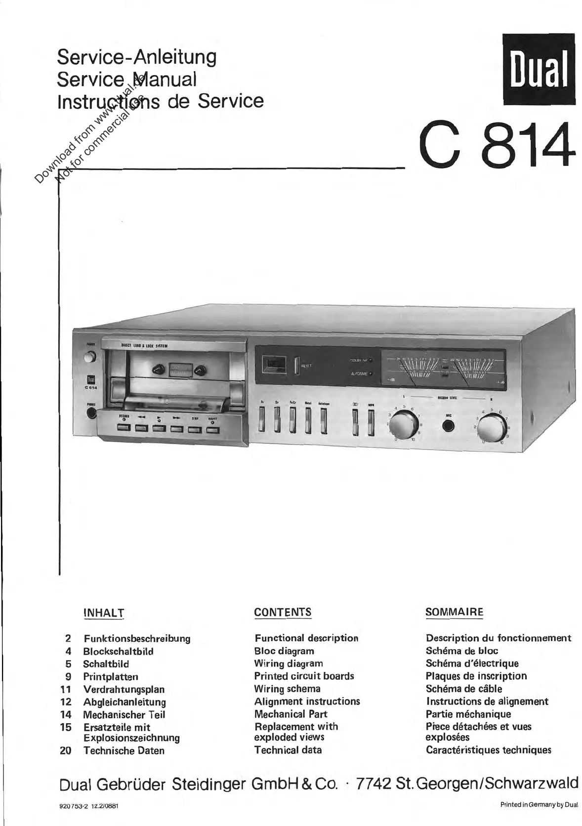
Service
-Anleitung
Service
Manual
lnstructions
de
Service
Dual
814
INHALT
CONTENTS
SOMMA
I
RE
2
Funktionsbeschreibung
Functional
description
Description
du
fonctionnement
4
Blockschaltbild
Bloc
diagram
Schema
de
bloc
5
Schaltbild
VViring
diagram
Schema
d'electrique
9
Printplatten
Printed
circuit
boards
Plaques
de
inscription
11
Verdrahtungsplan
VViring
schenna
Schema
de
cäble
12
Abgleichanleitung
Alignment
instructions
lnstructions
de
alignement
14
Mechanischer
Teil
Mechanical
Part
Partie
möchanique
15
Ersatzteile
mit
Replacement
with
Piece
detachees
et
vues
Explosionszeichnung
exploded
views
explosees
20
Technische
Daten
Technical
data
Caracteristiques
techniques
Dual
Gebrüder
Steidinger
GmbH
&
Co.
•
7742
St.
Georgen/Schwarzwald
920
753-2
12.2/0881
Printed
in
Germany
by
Dual
Download from www.dual.de
Not for commercial use
Product specificaties
| Merk: | Dual |
| Categorie: | Niet gecategoriseerd |
| Model: | C 814 |
Heb je hulp nodig?
Als je hulp nodig hebt met Dual C 814 stel dan hieronder een vraag en andere gebruikers zullen je antwoorden
Handleiding Niet gecategoriseerd Dual

6 December 2025
30 November 2025
30 November 2025
29 September 2025
30 Januari 2025
30 Januari 2025
30 Januari 2025
30 Januari 2025
8 November 2024
7 November 2024
Handleiding Niet gecategoriseerd
Nieuwste handleidingen voor Niet gecategoriseerd
23 April 2026
23 April 2026
23 April 2026
23 April 2026
23 April 2026
23 April 2026
23 April 2026
23 April 2026
23 April 2026
23 April 2026