CTA Digital PAD-PARFGRA Handleiding


Bekijk gratis de handleiding van CTA Digital PAD-PARFGRA (3 pagina’s), behorend tot de categorie Niet gecategoriseerd. Deze gids werd als nuttig beoordeeld door 3 mensen en kreeg gemiddeld 4.4 sterren uit 2 reviews. Heb je een vraag over CTA Digital PAD-PARFGRA of wil je andere gebruikers van dit product iets vragen? Stel een vraag

Pagina 1/3
718-963-9845
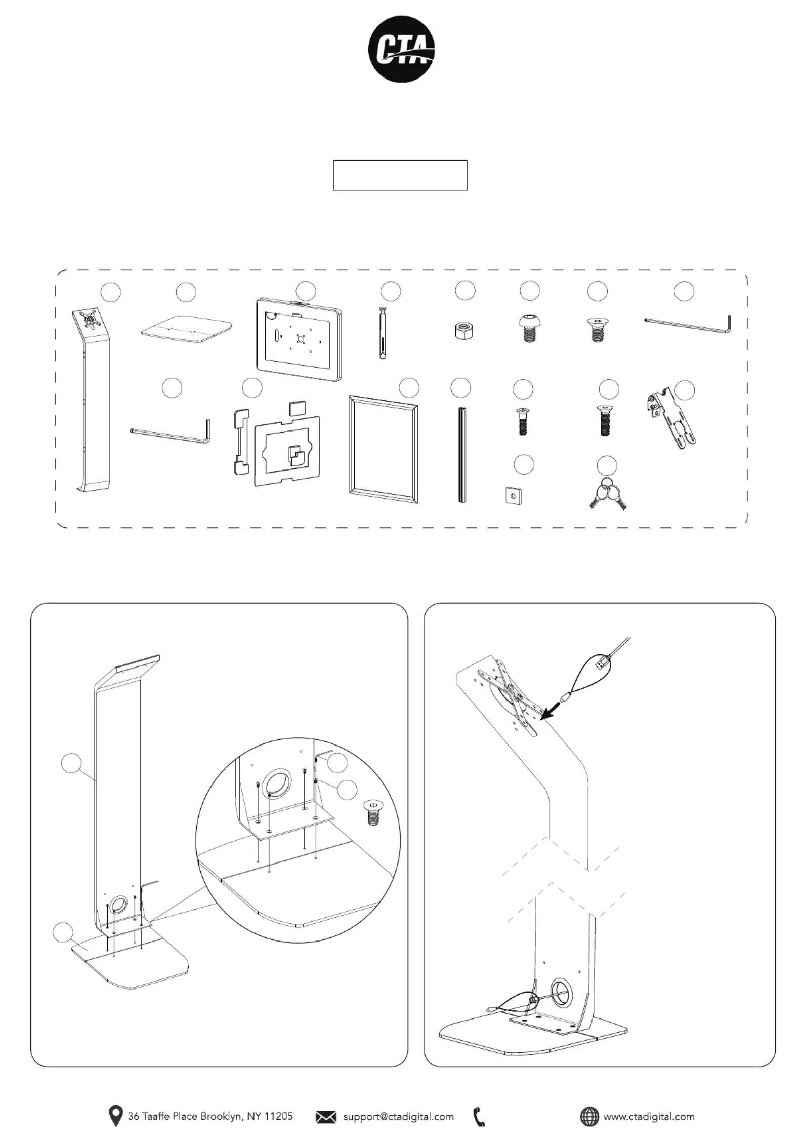
Premium Graphic Sign Floor Stand
With Security Enclosure
PAD-PARFGRA
INSTRUCTION - MANUAL
CONTENTS:
A
F
x4
G
x4
INSTRUCTIONS:
D
Metal
Anchor
x2
M5 Nut
E
x2
x1
J
Foam Adapter &
Sheet Bundle
x1
x1
K
x1
L
M5x18
x4
N
M4x16
x2
M
M5 Allen Key
x1
H
x1
O
x2
P
M6 Allen Key
x1
I
x1
B
1. Assembling floorstand base
1A. Allign the holes at the bottom of the body (A) with holes on the base
(B) and rotate in screws (F) with provided allen tool (K) until securely
tightened. Shown above.
2B. When the cable reaches
the bottom of the stand, pull
through the hole at the stand
back and remove the
weighted pendant as shown.
2A. To route a charge cable
through the stand, attach the
weighted pendant to your
charge cable, then pass
through the cutout at the top
of the stand.
M6 p1-x4
2. Cable routing
A
B
F
K
C
x1
Q
x2
718-963-9845
4. Attaching VESA component
4A. Identify the VESA component (O) and slide the
back side screw grooves to the U-shape of the
front of the center bracket (L) as illustrated above.
4B. When desired location is located, use provided
tool (H) and rotate in front of screws as illustrated
above until securely fastened.
O
L
H
3. Attaching bracket to graphic panel
L
3A. Grab both mounting component (P) and
slide it through the bracket (L) as illustrated.
P
L
K
M
3B. Align mounting component (L) with the holes of graphic panel (K). Rotate
in two screws (M) with screwdriver (not included) until securely fastened.
5. Attaching enclosure and ADD-GRAPHIC to VESA plate on base
N
H
5A. Remove floorstand VESA component unscrewing the screws (N) using provided tool (H).
Insert VESA bracket of graphic add-on (C). Align VESA holes of both components. Rotate back
screws (F) using provided tool (H) until securely fastened. Then align VESA holes of enclosure-
with the threaded VESA holes in base and rotate in screws until securely fastened.
O
F
718-963-9845
7. Attaching Graphic Decal
8. Adjusting Tilt Angle
I
O
8A. Using provided tool (I), rotate side screws of VESA component
(O) to loosen. Adjust to prefered tilt angle. Then rotate opposite
way to tighten until securely fastened.
7A. Using your hands, open the edges of the frame. Place adhesive
graphic onto surface as illustrated. Then close the edges of the
frame when finished.
10A. Using a power drill or similar (note provided) that is the same size as your metal anchor - create a cavity in the floor. Insert the base part
of the metal anchor (D), and screw in the nail component of the metal anchor (D) from above with a screwdriver (not provided) until securely
tightened. Repeat for all holes.
10. (Optional). Bolting floor stand down
D
D
**Screwdriver for Illustration
Purposes Only and Not Included
6. Setting up device & enclosure
**Tablet shown for illustration
and NOT INCLUDED.
6A. Insert the appropriate foam
piece (J) that is compatible with
your tablet.
6B. Insert tablet as shown. Plug in
power cable to tablet and cable
route through the back.
6C. Place the appropriate provid-
ed tablet cover (J) to match your
tablet.
6D. Close the enclosure and
lock it with the included set
of keys (Q).
J
J
Q
9. Removing Plastic Covers
9A. Please remove the rubber front cover if you want to use iPad 10th with fron camera exposed as well back cover to expose rear camera.
Front Back


Product specificaties

Merk: CTA Digital
Categorie: Niet gecategoriseerd
Model: PAD-PARFGRA

Heb je hulp nodig?

Als je hulp nodig hebt met CTA Digital PAD-PARFGRA stel dan hieronder een vraag en andere gebruikers zullen je antwoorden