Costar CTT2S28VI Handleiding
Costar
Bewakingscamera
CTT2S28VI
Bekijk gratis de handleiding van Costar CTT2S28VI (2 pagina’s), behorend tot de categorie Bewakingscamera. Deze gids werd als nuttig beoordeeld door 23 mensen en kreeg gemiddeld 4.2 sterren uit 12 reviews. Heb je een vraag over Costar CTT2S28VI of wil je andere gebruikers van dit product iets vragen? Stel een vraag
Pagina 1/2

2MP, B2.8 or MFZ2.8-12mm AI, IR,
WDR, 12VDC/24VA, IP66
Issue:1.0
TVI Turret Camera
Quick Setup Guide
Special Announcement
, For more information please refer to website.
Fully understand this document before using this device, and
strictly observe rules in this document when using this device. If
you install this device in public places, provide the tip "You have
entered the area of electronic surveillance" in an eye-catching
place. Failure to correctly use electrical products may cause fire
and severe injuries.
It alerts you to moderate dangers which, if not
avoided, may cause minor or moderate injuries.
It alerts you to risks. Neglect of these risks may
cause device damage, data loss, device
performance deterioration, or unpredictable results.
It provides additional information.
ŸStrictly observe installation requirements when installing the
device. The manufacturer shall not be held responsible for
device damage caused by users' non-conformance to these
requirements.
ŸStrictly conform to local electrical safety standards and use
power adapters that are marked with the LPS standard when
installing and using this device. Otherwise, this device may be
damaged.
ŸUse accessories delivered with this device. The voltage must
meet input voltage requirements for this device.
ŸIf this device is installed in places with unsteady voltage, ground
this device to discharge high energy such as electrical surges in
order to prevent the power supply from burning out.
ŸWhen this device is in use, ensure that no water or any liquid
flows into the device. If water or liquid unexpectedly flows into
the device, immediately power off the device and disconnect all
cables (such as power cables and network cables) from this
device.
ŸDo not focus strong light (such as lighted bulbs or sunlight) on
ŸAvoid heavy loads, intensive shakes, and soaking to prevent
damages during transportation and storage. The warranty does
not cover any device damage that is caused during secondary
packaging and transportation after the original packaging is
taken apart.
ŸProtect this device from fall-down and intensive strikes, keep the
device away from magnetic field interference, and do not install
the device in places with shaking surfaces or under shocks.
ŸClean the device with a soft dry cloth. For stubborn dirt, dip the
cloth into slight neutral cleanser, gently wipe the dirt with the
cloth, and then dry the device.
ŸDo not jam the ventilation opening. Follow the installation
instructions provided in this document when installing the device.
ŸKeep the device away from heat sources such as radiators,
electric heaters, or other heat equipment.
ŸKeep the device away from moist, dusty, extremely hot or cold
places, or places with strong electric radiation.
ŸIf the device is installed outdoors, take insect- and moisture-
proof measures to avoid circuit board corrosion that can affect
monitoring.
ŸRemove the power plug if the device is idle for a long time.
ŸBefore unpacking, check whether the fragile sticker is damaged.
If the fragile sticker is damaged, contact customer services or
sales personnel. The manufacturer shall not be held responsible
for any artificial damage of the fragile sticker.
ŸAll complete products sold by the manufacturer are delivered
along with nameplates, quick setup guide and accessories after
strict inspection. The manufacturer shall not be held responsible
for counterfeit products.
ŸThe manufacturer will update this manual according to product
function enhancement or changes and regularly update the
software and hardware described in this manual. Update
information will be added to new versions of this manual without
prior notice.
ŸThis manual may contain misprints, technology information that
is not accurate enough, or product function and operation
description that is slightly inconsistent with the actual product,
the final interpretation of company is as a standard.
ŸThis manual is only for reference and does not ensure that the
information is totally consistent with the actual product. For
consistency, see the actual product.
Precautions
Open the package, check the appearance of product for no
obvious damage, and confirm the item list for table 1-1 is
consistent.
Table 1 1- Packing list
Component Quantity Remark
TVI Turret Camera
Black stainless self-tapping screw
PA4.0×35mm
Swell plastic button 10.8×39mmφ
Black stainless self-tapping screw
PA4.0×30mm
L wrench
Installation location sticker
Quick Setup Guide
1
4
3
1
1
1
NOTE
NOTE
this device. Otherwise, the service life of the image sensor may
be shortened.
ŸIf this device is installed in places where thunder and lightning
frequently occur, ground the device nearby to discharge high
energy such as thunder strikes in order to prevent device
damage.
T15 screwdriver
Swell plastic button S8×30mm
1
2 3 Camera Dimensions Unit:mm.
Figure 2 3- Fixed focus small Eyeball
Different device may have different dimensions, please refer
to the actual product.
NOTE
CAUTION
WARNING
WARNING
CAUTION
O
O
O
OOp
p
p
ppe
e
e
een P
n P
n P
n Pn Pa
a
a
aac
c
c
cck
k
k
kka
a
a
aag
g
g
gge E
e E
e E
e Ee Ex
x
x
xxa
a
a
aam
m
m
mmi
i
i
iin
n
n
nna
a
a
aat
t
t
tti
i
i
iio
o
o
oon
n
n
nn
12.2 Function Keys
Users can call OSD main menus through multi function switch
control keys, and check and set camera parameters, function keys
is shown as figure 2-2.
Figure 2 2- Function keys
Up
Down
Left Right
SET
DN
UP
Operation de scription
SET key: It is used to enter OSD menus or select menu items
when you press this key in the middle of the multi function switch.
UP/DOWN keys: The UP and DOWN keys are used to select menu
items upwards and downwards by prodding the multi function
switch upwards and downwards, the menu items rapidly roll
upwards and downwards accordingly;
LEFT/RIGHT keys: The LEFT and RIGHT keys are used to select
menu items horizontally or modify parameters by prodding the
multi function switch towards the left or the right, the parameter
values will rapidly decrease or increase.
Press and hold the LEFT button for 5s to switch to AHD mode.
Press and hold the RIGHT button for 5s to switch to TVI mode.
Press and hold the UP button for 5s to switch to CVBS mode.
Press and hold the DOWN button for 5s to switch to CVI mode.
94
84
48.5
48.5
NOTE
The detail operation of OSD refer to Camera OSD Operation
Guide.
Alternative
Alternative
Figure2-4 Zoom lens large eyeball2
120
105
70
70
D
D
D
DDe
e
e
eev
v
v
vvi
i
i
iic
c
c
cce S
e S
e S
e Se St
t
t
ttr
r
r
rru
u
u
uuc
c
c
cct
t
t
ttu
u
u
uur
r
r
rre
e
e
ee2
Figure 2 1- Multi-head cable
1
2
3
POW ER
Table 2-1 Multi-head cable description
2
Power supply
Connects to a 12V 10% direct ±
current (DC) power supply.
(A 24V optional)C
1
ID Core Description Remark
4
3
HD C VBS
4
Video Output Output TVI Analog video signal.
Video Output Output CVBS Analog video signal.
Five-way switch
button
OSD menu settings,and video source
switching
NOTENOTE
OSD menu For details, refer to "Camera OSD Operation Guide".
2.1 Device Ports
——CVBS(Yellow)
——TVI(Green)
——12V DC or 24V AC
UP
DN
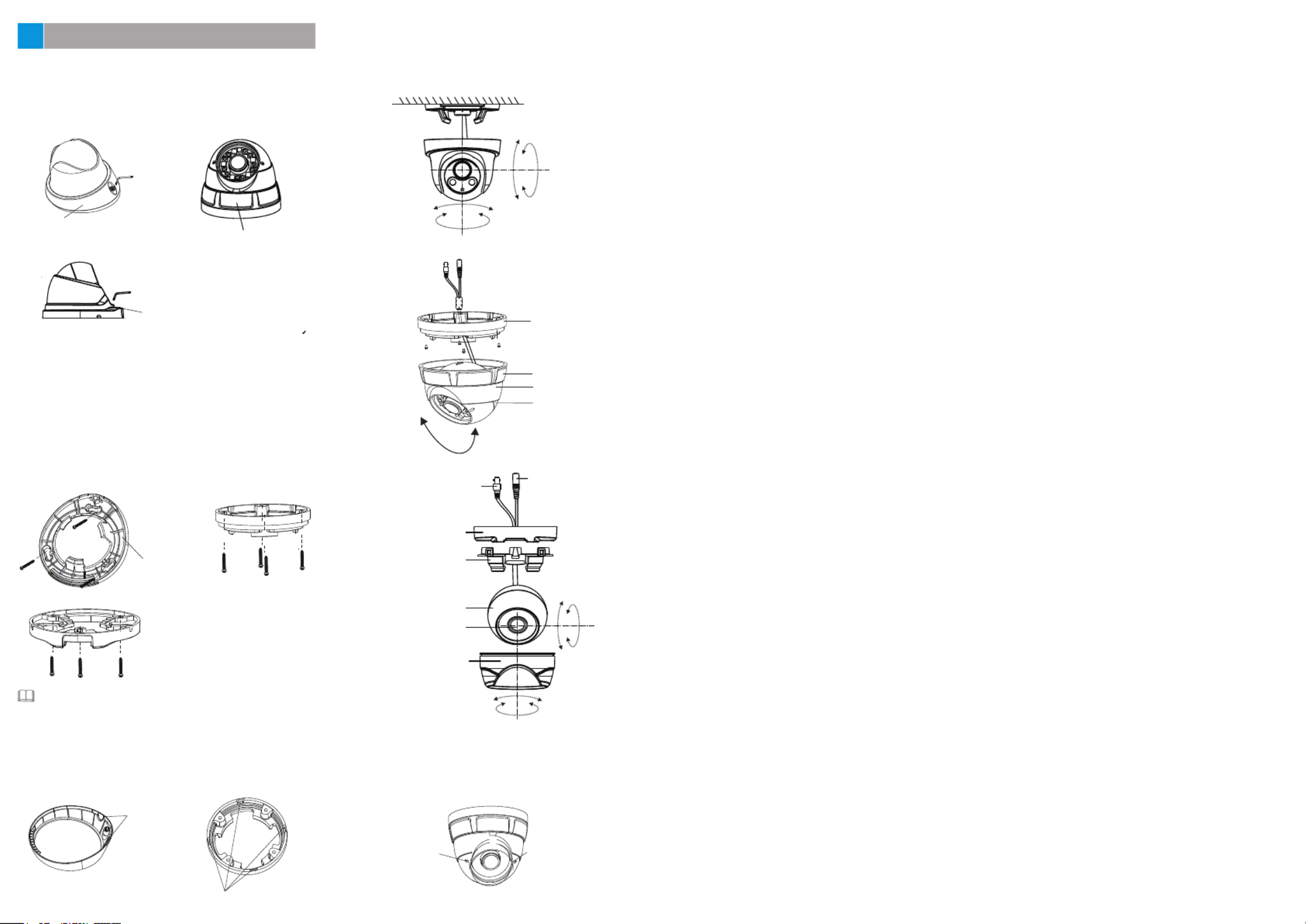
you can route cables from the top or from aside. If you use the top
routing method, drill a hole in the surface first. If you use the aside
routing method. When you route cables from aside, please cut the
compression ring outlet, as shown in figure 3-3, and route the cable
out from the side gap at the bottom of the camera.
NOTE
Outlet
F 3-3 igure Cutting the c ompression ring outlet
Step 4 Install the dome shell and the compression ring on the mount-
ing base, adjust the position so that the camera faces the moni-
tored area, then tighten the screw, as shown in figure 3-4.
Figure 3 1 - Removing compression ring
screwdriver
Compression ring
Step 2 Stick the I nstallation location sticker on the ceiling or wall,
Drill three holes based on t he marks on the st icker. Drive
the swell plastic buttons into the holes.
Step 3 Fix the camera mounting base to the mou nting surface, by
use of self-tapping screws, as shown in fi gure 3-2.
Mounting base
Figure 3 2- Fixing the mounting base
Installation Steps:
Step 1 Open a package, take out the camera and the accessories,
unscrew the compression ring or use the screwdriver t o
loosen the screw, remove the compression ring, as shown
in figure 3-1 .
3D
D
D
DDe
e
e
eev
v
v
vvi
i
i
iic
c
c
cce I
e I
e I
e Ie In
n
n
nns
s
s
sst
t
t
tta
a
a
aal
l
l
lll
l
l
lla
a
a
aat
t
t
tti
i
i
iio
o
o
oon
n
n
nn
screwdriver
Compression ring
Compression ring
Outlet
Dome cover rotating shaft
Dome shell
rotating shaft
Figure 3-4 Installing and djusting camera
Mounting base
Compression ring
Dome shell fixed base
Dome shell
Power connector
Video connector
Mounting base
Plastic supporting frame
Dome shell
Lens
Compression ring
Foucs
Zoom
F 5igure3- Adjusting view angle and focal length
Step 5 For camera of zoom lens, adjust view angle and focal
length by using an adjusting tool, as shown in figure 3-5 .
Product specificaties
| Merk: | Costar |
| Categorie: | Bewakingscamera |
| Model: | CTT2S28VI |
Heb je hulp nodig?
Als je hulp nodig hebt met Costar CTT2S28VI stel dan hieronder een vraag en andere gebruikers zullen je antwoorden
Handleiding Bewakingscamera Costar

8 Februari 2024

8 Februari 2024

8 Februari 2024

8 Februari 2024

8 Februari 2024

8 Februari 2024

8 Februari 2024

8 Februari 2024

8 Februari 2024

8 Februari 2024
Handleiding Bewakingscamera
- Dahua Technology
- EtiamPro
- POSline
- Kramer
- Marquant
- Lorex
- Nivian
- AVerMedia
- Vivotek
- Quantum
- Trendnet
- Arenti
- Avidsen
- InfiRay
- Aldi
Nieuwste handleidingen voor Bewakingscamera

5 Augustus 2025

5 Augustus 2025
5 Augustus 2025

5 Augustus 2025

5 Augustus 2025

5 Augustus 2025

5 Augustus 2025

5 Augustus 2025

5 Augustus 2025

5 Augustus 2025