Chamberlain 041-0182-000 Handleiding
Chamberlain
Niet gecategoriseerd
041-0182-000
Bekijk gratis de handleiding van Chamberlain 041-0182-000 (6 pagina’s), behorend tot de categorie Niet gecategoriseerd. Deze gids werd als nuttig beoordeeld door 107 mensen en kreeg gemiddeld 4.5 sterren uit 54 reviews. Heb je een vraag over Chamberlain 041-0182-000 of wil je andere gebruikers van dit product iets vragen? Stel een vraag
Pagina 1/6

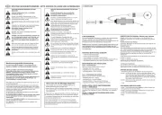
End Panel Replacement
Repair Parts 041-0182-000 and 041-0183-000
Installation
You will need:
• 1/4" magnetic nut driver
• Long-nosed pliers
• 1/4" long-shafted magnetic nut driver and socket
• Phillips head screwdriver
• Flathead screwdriver
The images throughout this manual are for reference only and your
product may look different.
1. Disconnect the electrical and battery power (if applicable) to the
garage door opener. Remove the battery and place in a safe location.
2. Remove the control panel door from the opener. (A)
a. Squeeze hinges toward each other.
b. Remove the control door panel from the hinge setting, and place in
a safe location.
c. Remove the end panel cover from the end panel. (B)
3. Remove the end panel from the opener. (C)
4. Attach the provided blank label to the new end panel, and copy (D)
important product information from the original end panel.
To prevent possible SERIOUS INJURY or DEATH:
• Disconnect ALL electric and battery power BEFORE performing
ANY service or maintenance.
To prevent damage to the receiver/logic board, DO NOT touch printed
circuit board of replacement receiver/logic board during installation.
ALWAYS wear protective gloves and eye protection when changing
the battery or working around the battery compartment.
WARNING: This product can expose you to chemicals including
lead, which are known to the State of California to cause cancer
or birth defects or other reproductive harm. For more information
go to www.P65Warnings.ca.gov.
Logic Board
End Panel Receiver
Logic Board
End Panel Cover
Control Panel Door
PART
NUM
B
ER:
SE
RIAL NUMBE R
DAT
E:
SS
IC: 2666 A -
FCC
ID:
100W Max
26W
Max
CONT
A
INS
:
FC
C ID: C
OF
WMNBM11
IC: 1
02
3
9A-W
M
NB
M1
1
®
BC
D
RED
WHITE
WHITE
GREY
Wire
Channel
Antenna
wires
Logic Board
End Panel
Wire
Harnesses
Receiver
Logic
Board
Antenna wires
routing
To insert or
remove the
wires from the
terminal, push
in the tab with a
screwdriver tip.
A
LiftMaster Brand Garage Door Opener
5. Install the new end panel.
6. Attach the end panel cover
7. Attach the control door panel.
8. Reconnect power to the opener.
9. Test of the safety reverse system. Refer to the owner’s manual.

© 2021, LiftMaster
All rights reserved
Tous droits réservés
114-5528-000 Todos los derechos reservados

Reemplazo del panel del extremo
Piezas de repuesto 041-0182-000 y 041-0183-000
Instalación
Necesitará:
• Llave de tuerca magnética de 1/4"
• Pinza de punta
• Llave de tuerca magnética de cuello largo de 1/4" y vaso
• Destornillador de cabeza Phillips
• Destornillador plano
Las imágenes utilizadas en este manual son solo como referencia y su
producto puede verse diferente.
1. Desconecte la alimentación eléctrica y de batería (si corresponde) al
abrepuertas de garaje. Quite la batería y colóquela en un lugar seguro.
2. Quite la puerta del panel de control del abrepuertas. (A)
a. Apriete las bisagras para que se unan.
b. Quite la puerta del panel de control del conjunto de bisagras y
colóquela en un lugar seguro.
c. Quite la cubierta del panel del extremo. (B)
3. Quite el panel del extremo del abrepuertas. (C)
4. Coloque la etiqueta en blanco (D) en el nuevo panel del extremo y copie
la información importante del producto del panel del extremo original.
Para evitar posibles LESIONES GRAVES o la MUERTE:
• Desconecte TODA alimentación eléctrica y de batería ANTES de
realizar CUALQUIER servicio o mantenimiento.
Para evitar daños al receptor/tarjeta lógica, NO toque el circuito
impreso de la tarjeta en el receptor/tarjeta lógica de repuesto durante
la instalación.
Use SIEMPRE guantes protectores y protectores para la vista al
cargar la batería o al trabajar cerca del compartimento de la batería.
ADVERTENCIA: Este producto podría exponerlo a sustancias
químicas, incluido el plomo, que el estado de California conoce
como causantes de cáncer, defectos de nacimiento u otros
daños reproductivos. Para obtener más información, visite
www.P65Warnings.ca.gov.
Panel del extremo
de la tarjeta lógica Tarjeta lógica
del receptor
Cubierta del panel
del extremo
Puerta del panel
de control
PART
NUM
B
ER:
S
ERIAL NUMBER
DATE:
SS
IC: 2666 A -
FCC ID:
100W
Max
26W Max
C
ONT
A
INS
:
FC
C ID: C O
FWMNBM1 1
IC:
102
3
9A-W
M
NB
M1
1
®
BC
D
ROJO
BLANCO
BLANCO
GRIS
Canal
de cable
Cables de
la antena
Panel del extremo
de la tarjeta lógica
Arnés
del cable
Tarjeta
lógica del
receptor
Cómo pasar los cables
de la antena
Para insertar o
quitar los cables
del terminal,
empuje la pestaña
con la punta de
un destornillador.
A
Abrepuertas de garaje marca LiftMaster
5. Instale el panel del extremo nuevo.
6. Coloque la cubierta del panel del extremo
7. Coloque la puerta del panel de control.
8. Vuelva a conectar la alimentación al abrepuertas.
9. Pruebe el sistema de inversión de seguridad. Consulte el manual del
propietario.
Product specificaties
| Merk: | Chamberlain |
| Categorie: | Niet gecategoriseerd |
| Model: | 041-0182-000 |
Heb je hulp nodig?
Als je hulp nodig hebt met Chamberlain 041-0182-000 stel dan hieronder een vraag en andere gebruikers zullen je antwoorden
Handleiding Niet gecategoriseerd Chamberlain
11 Augustus 2025
6 Juli 2025
16 Juni 2025
15 Juni 2025

12 November 2024

10 Juni 2024

27 Mei 2024

30 Juni 2023

16 Mei 2023
Handleiding Niet gecategoriseerd
- Ruggard
- Rane
- Pioneer
- Kugoo
- Eura
- Master
- Loxone
- VS Sassoon
- REVITIVE
- BrightSign
- PTZ Optics
- Perma
- Integra
- Princeton Tec
- UClear
Nieuwste handleidingen voor Niet gecategoriseerd
15 Augustus 2025
15 Augustus 2025

15 Augustus 2025
15 Augustus 2025

15 Augustus 2025
15 Augustus 2025
15 Augustus 2025
15 Augustus 2025
15 Augustus 2025
15 Augustus 2025
