Carrier Comfort Pro 33CSCNACHP-01 Handleiding

Carrier Thermostaat Comfort Pro 33CSCNACHP-01

Lees hieronder de đź“– handleiding in het Nederlandse voor Carrier Comfort Pro 33CSCNACHP-01 (4 pagina's) in de categorie Thermostaat. Deze handleiding was nuttig voor 30 personen en werd door 2 gebruikers gemiddeld met 4.5 sterren beoordeeld

Pagina 1/4
Manufacturer reserves the right to discontinue, or change at any time, specifications or designs without notice and without incurring obligations.
Catalog No. 04-53330023-01 Printed in U.S.A. Form 33CS-23SO Pg 1 8-11 Replaces: New
Owner’s Manual
Part Number 33CSCNACHP-01
SAFETY CONSIDERATIONS
Read and follow manufacturer instructions carefully. Fol-
low all local electrical codes during installation. All wiring
must conform to local and national electrical codes. Improper
wiring or installation may damage thermostat.
Recognize safety information. This is the safety alert sym-
bol . When the safety alert symbol is present on equipment
or in the instruction manual, be alert to the potential for person-
al injury.
Understand the signal words DANGER, WARNING, and
CAUTION. These words are used with the safety alert symbol.
DANGER identifies the most serious hazards which will result
in severe personal injury or death. WARNING signifies a haz-
ard which could result in personal injury or death. CAUTION
is used to identify unsafe practices which would result in minor
personal injury or property damage.
GENERAL
Carrier's Comfort Pro non-programmable thermostats are
wall-mounted, low-voltage thermostats which maintain space
temperature by controlling the operation of a heating and/or air
conditioning system. This thermostat can be used with a heat
pump, air conditioner or water source heat pump operation. A
variety of features are provided including battery operation,
separate heating and cooling set points, auto changeover, key-
pad lockout, and backlighting.
OPERATION
Thermostat Button Identification — The follow-
ing buttons are located on the thermostat display. See Fig. 1 for
button locations.
• FAN (1) — Selects whether the fan operates continu-
ously (on) or only when needed for heating or cooling
(auto)
• MODE (2) — Selects whether thermostat is set for heat-
ing, cooling, emergency heat, auto (heat and cool as
needed), or off
• UP (3) — Increases the temperature or adjusts the screen
selection up when setting advanced features
• DOWN (4) — Decreases the temperature or adjusts the
screen selection down when setting advanced features
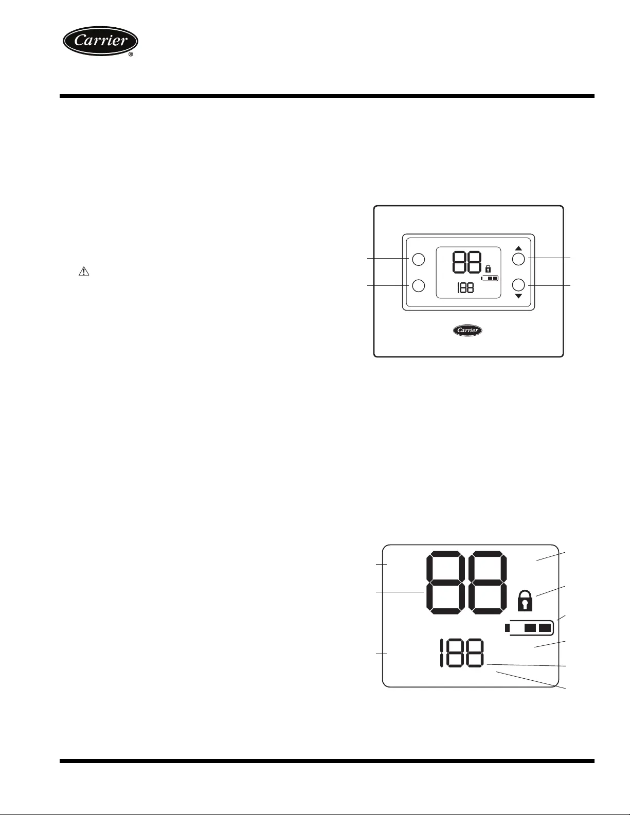
Thermostat On-Screen Indicators — The follow-
ing on-screen indicators can be displayed on the thermostat dis-
play. See Fig. 2 for location of indicators.
• Fan mode - on or auto (1)
• Current temperature (2)
• Mode (3)
• Fahrenheit or Celsius units (4)
• Keypad is locked (no padlock means unlocked) (5)
• Battery strength indicator (6)
• Auxiliary heat (7)
• Current set point (8)
• Second stage is active (cooling or heating if available)
(9)
1
2
4
3
mode
fan
Em
heat
cool
auto
off
auto
fan
on
aux heat
on
2
°F
°C
set at
actual temp
Fig. 1 — Thermostat Button Identification
a33-9223
Em
heat
cool
auto
off
auto
fan
on
aux heat
on
2
°F
°C
set at
actual temp
3
2
1
4
5
6
7
8
9
Fig. 2 — Thermostat On-Screen Indicators
a33-9222
Comfort™ Pro
Non-Programmable
Commercial Thermostat
2
Setting Heating and Cooling Temperatures —
The thermostat is installed with the heating set at 68 F and the
cooling set at 78 F. Perform the following procedure to change
the temperature setting:
1. To change the heating temperature, press the mode but-
ton on the left until the screen displays “heat”.
2. Press the up or down button located on the right side of
the display until the desired temperature is reached.
3. To change the cooling temperature, press the mode but-
ton on the left until the screen displays “cool”.
4. Press the up or down button located on the right side of
the display until the desired temperature is reached.
Turning Heating and Cooling System Off —
To use the thermostat to turn the heating and cooling system
off, press the mode button until the display shows “off” in the
upper left corner.
Advanced Programming — The user can customize
two different features on the thermostat, the Fahrenheit or Cel-
sius display and the backlighting of the thermostat.
FAHRENHEIT OR CELSIUS DISPLAY — The thermostat
is preset to display the temperature in degrees Fahrenheit. The
user can change the display to Celsius if desired. To change the
display, perform the following procedure:
1. Press and hold the mode button for about three seconds.
The screen will display flashing “U1”. Press the mode
button and the letter F will flash.
2. Press the up or down button on the right to change it
from F (Fahrenheit) or C (Celsius).
3. Press the fan button on the left to exit this screen.
BACKLIGHTING — The thermostat can be set to have the
backlighting either off or on. To change the backlighting selec-
tion, perform the following procedure:
1. Press and hold the mode button for about three seconds.
The screen will display “U1” and the letter F or C in the
center.
2. Press the up button once. The display will show a flash-
ing “U2”.
3. Press the mode button again and the On or Off will flash.
4. Press the up or down button located on the right side of
the display to change it from Off to On or On to Off.
5. Press the fan button on the left to exit this screen.
Using the Fan — The thermostat is factory configured so
that the fan runs only when heating or cooling is required (Fan
Auto mode). The setting can be changed so that the fan runs
continuously (Fan On mode). To change the fan setting:
1. Press the fan button on the left side. The “fan on” will ap-
pear in the lower left corner of the display.
2. Press the fan button again to change settings.
Auto Changeover — The thermostat displays one of
five modes: heat, cool, Em heat, heat cool (auto mode) and off.
When the mode selection is in auto mode, the system is al-
lowed to switch from heating to cooling or from cooling to
heating to maintain the temperature set points.
Unlocking the Keypad — The thermostat is locked
when the padlock symbol is shown on the thermostat display.
A locked thermostat will inhibit a user from making adjust-
ments.
The method by which the thermostat is unlocked is config-
ured by the installer. Three unlocking options are available:
1. The user must simultaneously depress up and down but-
tons for 5 seconds.
2. If a set of dashes are displayed, then a four-digit pass code
must be entered by the user.
3. The user must simultaneously depress the up and down
buttons for 5 seconds, and then enter a four-digit pass
code.
Auxiliary Heat — This option is available for all of the
equipment types except cool only. When the auxiliary heat is
active "aux heat" will be displayed and the supplemental heat is
used to meet the demand in the space. The heater will turn on
automatically.
Using Emergency Heat — Emergency heat is used
when the heat system cannot keep up with demand. If the heat
pump compressor that works with auxiliary heat fails, or if the
heat pump is not working at all, the emergency heat can be
used. To set the thermostat to use emergency heat, press the
mode button until the display shows Em Heat in the upper left
corner of the display.
Power Outage — If the building loses electricity, the
thermostat will not need to be reprogrammed. The settings are
retained in memory.
TROUBLESHOOTING
There are system error messages that may appear on the
thermostat screen. See text below for possible system error
messages and their meaning.
E4 (Memory Failure) — The memory has failed and the
thermostat will return to the default factory settings. Call your
heating and cooling dealer.
Space Temperature Sensor Failure — If the
space sensor reads less than –50 F or greater than 150 F for 60
consecutive seconds, the sensor is considered failed.
If the sensor has failed, the O/B, Y2, Y1 and W outputs turn
off and the space temperature display will show "- -". The fan
will continue to run if the user has set the fan selection to "fan
on".
Battery Icon — The battery icon appears on the display
only when the batteries start to lose power. Replace the batter-
ies when one bar is displayed inside the battery shell. If the
thermostat is battery powered and is just a silhouette with no
black bars, the thermostat will slowly lose functions until it
does not work at all.
Changing Batteries — The thermostat can be powered
by the HVAC equipment or by battery power. If there is no
lighting until the user touches a button, it is battery powered.
When the thermostat uses electricity, the batteries (if installed)
take over if the electricity goes out.
When powered by batteries, the thermostat's two AA batter-
ies should last about one year. When the batteries have lost
about one-third of their power, a battery icon shows up on the
display in the upper right corner with two black bars. If two-
thirds of battery power is lost, the battery icon will display one
black bar. As the batteries get weaker, the icon goes down to
one bar and then none. When the battery icon is less than full,
backlight function will be lost. When the batteries are com-
pletely dead, the thermostat will be unusable.
It is recommended that the batteries be replaced at the one
bar level with two AA alkaline batteries. Batteries are located
in the back of the thermostat, so the thermostat will have to be
removed from the wall.
To replace the batteries, perform the following procedure:
1. Locate the latch at the top of the thermostat. The latch is
located at the center of the top rim.
3
2. Press the latch down. This will disconnect the thermostat
from the top of the wall plate.
NOTE: The HVAC equipment will shut down.
3. Remove the thermostat from the wall bracket completely
by moving it slightly toward you and lifting it up and off
the lip on the lower edge of the wall bracket.
4. Set the thermostat face down on a flat surface. The batter-
ies are located in the lower right corner.
5. Remove and recycle the old batteries.
6. Install new batteries.
7. Replace the thermostat on the wall bracket by lining up
the two slots on the bottom edge of the back of the ther-
mostat with the two lips on the wall bracket.
8. The HVAC equipment will start back up based on the
previous configuration settings.


Product specificaties

Merk: Carrier
Categorie: Thermostaat
Model: Comfort Pro 33CSCNACHP-01

Heb je hulp nodig?

Als je hulp nodig hebt met Carrier Comfort Pro 33CSCNACHP-01 stel dan hieronder een vraag en andere gebruikers zullen je antwoorden


Handleiding Thermostaat Carrier

Handleiding Thermostaat

Nieuwste handleidingen voor Thermostaat