Broan 162 Handleiding
Broan
Ventilator
162
Bekijk gratis de handleiding van Broan 162 (8 pagina’s), behorend tot de categorie Ventilator. Deze gids werd als nuttig beoordeeld door 7 mensen en kreeg gemiddeld 4.8 sterren uit 4 reviews. Heb je een vraag over Broan 162 of wil je andere gebruikers van dit product iets vragen? Stel een vraag
Pagina 1/8

1
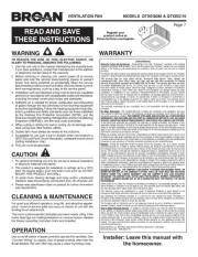
READ AND SAVE
THESE INSTRUCTIONS
MODELS 161 & 163 (TYPE IC) BULB HEATERS
MODELS 162 (TYPE IC) & 164 (TYPE IC) BULB
HEATER/FANS
LEA Y CONSERVE
ESTAS INSTRUCCIONES
CALENTADORES DE BOMBILLA MODELOS 161 &
163 (TIPO IC)
CALENTADOR DE BOMBILLA\VENTILADORES
MODELOS 162 (TIPO IC) & 164 (TIPO)
IMPORTANT INSTRUCTIONS
READ ALL INSTRUCTIONS BEFORE
INSTALLING OR USING THIS HEATER.
To reduce the risk of fire, electric shock, or injury to persons,
observe the following:
1. Use this unit only in the manner intended by the manufacturer.
If you have questions, contact the manufacturer at the
address or telephone number listed in the warranty.
2. Before servicing or cleaning unit, switch power off at service
panel and lock the service disconnecting means to prevent
power from being switched on accidentally. When the service
disconnecting means cannot be locked, securely fasten a
prominent warning device, such as a tag, to the service panel.
3. Installation work and electrical wiring must be done by a
qualified person(s) in accordance with all applicable codes
and standards, including fire-rated construction codes and
standards.
4. When cutting or drilling into wall or ceiling, do not damage
electrical wiring and other hidden utilities.
5. This heater is hot when in use. To avoid burns, do not let bare
skin touch hot surfaces. Keep combustible materials, such as
furniture, pillows, bedding, papers, clothes, etc. and curtains
at least 3 feet (0.9 m) from the front of the heater.
6. Extreme caution is necessary when any heater is used by
or near children or invalids and whenever the heater is left
operating and unattended.
7. Do not operate any heater after it malfunctions. Disconnect
power at service panel and have heater inspected by a
reputable electrician before reusing.
8. Do not use outdoors.
9. To disconnect heater, turn controls to off, and turn off power
to heater circuit at main disconnect panel (or operate internal
disconnect switch, if provided).
10. Do not insert or allow foreign objects to enter any ventilation
or exhaust opening, as this may cause an electric shock or
fire, or damage the heater.
11. To prevent a possible fire, do not block air intakes or exhaust
in any manner.
12. A heater has hot and arcing or sparking parts inside. Do not
use it in areas where gasoline, paint, or flammable vapors or
liquids are used or stored.
13. Use this heater only as described in this manual. Any other
use not recommended by the manufacturer may cause fire,
electric shock, or injury to persons.
14. This product is designed for installation in flat ceilings only.
DO NOT MOUNT THIS PRODUCT IN A WALL.
15. MODEL 161 ONLY: Install housing no closer than 6" from
side wall. For supply connections, use wire suitable for 75°C
minimum. Do not install insulation within 3 inches of top or
sides of housing.
16. To avoid electrical shock: Do not install unit in a tub or shower
enclosure or any location where it may come in contact with
water. Never place a switch where it can be reached from a
tub or shower.
17. Do not connect heater to dimmer switch or speed control.
18. This product must be grounded.
SAVE THESE INSTRUCTIONS
INSTALLER: Leave This Manual With The Home-
owner. HOMEOWNER: Use and Care Information
on Page 3.
INSTRUCCIONES IMPORTANTES
LEA TODAS LAS INSTRUCCIONES ANTES DE INSTALAR O
USAR ESTE CALENTADOR.
Para reducir el riesgo de incendios, descargas eléctricas o lesiones personales,
observe las siguientes precauciones:
1. Use la unidad solo de la manera indicada por el fabricante. Si tiene preguntas,
comuníquese con el fabricante a la dirección o al número telefónico que se
incluye en la garantía.
2. Antes de dar servicio a la unidad o de limpiarla, interrumpa el suministro eléctrico
en el panel de servicio y bloquee los medios de desconexión del servicio para
evitar que la electricidad se reanude accidentalmente. Cuando no sea posible
bloquear los medios de desconexión del servicio, fije firmemente una señal de
advertencia (como una etiqueta) en un lugar visible del panel de servicio.
3. El trabajo de instalación y el cableado eléctrico deben estar a cargo de personal
capacitado, de acuerdo con todos los códigos y normas correspondientes,
incluidos los códigos y normas de construcción específicos sobre protección
contra incendios.
4. Al cortar o perforar a través de la pared o del cielo raso, tenga cuidado de no
dañar el cableado eléctrico ni otros servicios ocultos.
5. Este calentador se calienta cuando se usa. Para evitar quemaduras, no deje que la
piel desnuda toque las superficies calientes. Mantenga materiales combustibles
como muebles, almohadas, ropa de cama, papeles, ropa, etc., así como las
cortinas, por lo menos a 3 pies (0.9 m) de la parte delantera del calentador.
6. Es necesario tener extremo cuidado cuando se use un calentador cerca de niños
o personas inválidas, y siempre que el calentador se deje funcionando y sin
atención.
7. No haga funcionar ningún calentador después de que presente una falla.
Desconecte la energía eléctrica en el panel de servicio y pida que un electricista
acreditado inspeccione el calentador antes de volverlo a usar.
8. No lo use en exteriores.
9. Para desconectar el calentador, mueva los controles a la posición de apagado
y desconecte la energía eléctrica al circuito del calentador en el panel de
desconexión principal (o active el interruptor de desconexión interna, si existe).
10. No inserte ni permita que objetos extraños entren en la abertura de ventilación
o de escape, pues esto puede ocasionar una descarga eléctrica, un incendio o
daños al calentador.
11. Para prevenir un posible incendio, no bloquee la entrada o salida del aire de
ninguna manera.
12. El calentador tiene piezas calientes y que pueden generar arcos eléctricos o
chispas en el interior. No lo use en áreas donde se use o almacene gasolina,
pintura o vapores o líquidos flamables.
13. Use este calentador solamente como se describe en este manual. Cualquier
otro uso no recomendado por el fabricante puede ocasionar un incendio, una
descarga eléctrica o lesiones a personas.
14. Este producto está diseñado solamente para instalarse en los techos planos.
NO MONTE ESTE PRODUCTO EN LA PARED.
15. SOLAMENTE MODELO 161: Instale la caja a no menos de 16 cm de la pared
lateral. Para conexiones de alimentación, use un alambre apropiado para un
mínimo de 75
o
C. No instale el aislamiento dentro de los 8 cm del tope o los
costados de la caja.
16. Para evitar golpe eléctrico: No instale la unidad en una bañera o recinto de ducha.
Nunca coloque un interruptor en un lugar que pueda ser alcanzado desde una
bañera o ducha.
17. No conecte el calentador a un variador de luz o control de velocidad.
18. Este producto debe estar conectado a tierra.
GUARDE ESTAS INSTRUCCIONES
INSTALADOR: Deje este manual con el dueño de casa. DUEÑO
DE CASA: Información del uso y mantenimiento en la página 3.

2
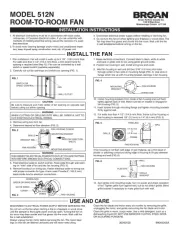
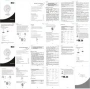
FIG. 1
CEILING MATE-
RIAL
MATERIAL DEL
CIELO RASO
GRILLE
REJILLA
DAMPER/DUCT CON-
NECTOR (162 & 164
ONLY)
AMORTIGUADOR/
ACOPLE DE CON-
DUCTO (162 Y 164
SOLAMENTE)
POWER
CABLE
CABLE DE
POTENCIA
HOUSING
CAJA
MOUNTING
BRACKET
SOPORTE DE
MONTAJE
CEILING
JOIST
VIGA DEL
CIELO
RASO
BULB(S)
BOMBILLA
FIG. 2
PLANNING
Choose the location for your heater. Refer to "IMPORTANT
INSTRUCTIONS" above.
MODELS 162 & 164 ONLY:
THE UNIT WILL OPERATE MOST EFFICIENTLY WHEN LO-
CATED WHERE THE SHORTEST POSSIBLE DUCT RUN AND
MINIMUM NUMBER OF ELBOWS WILL BE NEEDED. UNITS
ARE DESIGNED FOR USE WITH STANDARD 4" ROUND DUCT.
Note that two-bulb units (163 & 164) can be fitted with one
infrared bulb (for heat) and one reflector bulb (for light). Dual
or multi-controls can be used for separate control of bulbs
and/or exhaust fan. Purchase controls separately.
Follow these basic steps when installing this unit: (Fig. 1)
• Nailunittojoists.
• Attachductwork(Models162or164only).
• Connectpowercable.
• Fastengrilletohousing.
PREPARATION
1. Remove the unit from carton. Save carton for use
as plaster shield in rough-in installations.
2. Slide adjustable mounting brackets into bracket
channels on housing. (Fig. 2)
PLANIFICACION
Escoja un lugar para su calentador. Lea las instrucciones de “INS-
TRUCCIONES IMPORTANTES” que aparecen arriba.
MODELOS 162 & 164 SOLAMENTE:
LA UNIDAD FUNCIONARÁ EN FORMA MÁS EFICIENTE SI SE
UBICA EN UN LUGAR DONDE SE MINIMICE EL TENDIDO DE
CONDUCTOS Y EL NÚMERO DE CODOS. LAS UNIDADES HAN
SIDO DISEÑADAS PARA USO CON CONDUCTO REDONDO
ESTÁNDAR DE 10 cm.
Note que las unidades de dos bombillas (163 & 164) pueden mon-
tarse con una bombilla infrarroja (para la calefacción) y una bombilla
reflectora (para la luz). Se pueden usar controles dobles o múltiples
para un control separado de las bombillas y/o ventilador extractor
de aire. Los controles se compran por separado.
Al instalar esta unidad, siga los siguientes pasos básicos: (Fig. 1)
• Clavelaunidadalasvigas.
• Fijelosconductos(modelos162o164solamente).
• Conecteelcabledepotencia.
• Fijelarejillaalacaja.
PREPARACION
1. Saque la unidad de la caja de cartón. Guarde la caja de
cartón para su uso como escudo de yeso al principio de una
instalación.
2. Meta los soportes de montaje ajustables en los canales de
soporte en la caja. (Fig. 2)

3
FIG. 3
FIG. 4
FIG. 5
VERTICAL ADJUSTING
SCREWS
TORNILLOS DE AJUSTE
VERTICAL
WIRING BOX
CAJA DE CONEXIONES
INSTALLATION
WARNING: To reduce the risk of fire, do not store or use
gasoline or other flammable vapors and liquids in the
vicinity of the heater.
CAUTION: High temperature, risk of fire, keep electrical
cords, drapery, furnishings, and other combustibles
at least 3 feet (0.9 m) from the front of the heater and
away from the side and rear.
1. Position unit between joists and extend mounting
brackets.
2. Nail brackets firmly to joists. Bottom of brackets should
be positioned flush with joist bottom. (Fig. 3)
3. Brackets are factory-set for ½" thick ceiling mate-
rial. For thicker ceilings, loosen 4 vertical adjusting
screws and lower housing to appropriate thickness
on gauges. Tighten vertical adjusting screws firmly.
(Fig. 4)
ATTACH DUCTWORK
(MODELS 162 & 164 ONLY)
1. Snap the damper/duct connector onto housing. Make
sure that tabs on the connector lock in housing slots
and that gravity closes damper. (Fig. 4)
2. Attach 4" round duct to damper/duct connector and
run ductwork to the outside through a roof or wall
cap. Check damper to make sure it opens freely. Tape
all joints to make them secure and air tight. (Fig. 5)
INSTALACION
ADVERTENCIA: Para reducir el riesgo de incendio, no almacene
ni use gasolina u otros vapores y líquidos flamables en las
cercanías del calentador.
PRECAUCIÓN: Temperatura alta, el riesgo de incendio, mantenga
los cables eléctricos, cortinas, muebles y otros materiales
combustibles por lo menos 3 pies (0,9 m) del frente del calentador
y lejos de la cara y la parte trasera.
1. Coloque la unidad entre las vigas y extienda los soportes de montaje.
2. Clave firmemente los soportes en las vigas. Las partes de abajo
de los soportes deben colocarse a nivel con la parte de abajo de la
viga. (Fig. 3)
3. Los soportes se fijan en fábrica para material de cielo raso de un
grosor de 1,3 cm. Para cielo raso más gruesos, afloje 4 tornillos
de ajuste vertical y baje la caja al grosor apropiado según los
calibradores. Atornille firmemente los tornillos de ajuste vertical.
(Fig. 4)
FIJE LOS CONDUCTOS
(MODELOS 162 & 164 SOLAMENTE)
1. Enganche el acople de amortiguador/conducto en la caja. Compruebe
que las orejetas en el acople se enganchen en las ranuras de la caja
y que el amortiguador cierre por gravedad. (Fig. 4)
2. Fije el conducto redondo de 10 cm al acople del amortiguador/
conducto y saque el tendido de los conductos al exterior a través
de una cubierta de cielo raso o pared. Verifique que el amortiguador
se abra libremente. Ponga cinta alrededor de todas las uniones para
que queden seguras y herméticas.(Fig. 5)
Product specificaties
| Merk: | Broan |
| Categorie: | Ventilator |
| Model: | 162 |
Heb je hulp nodig?
Als je hulp nodig hebt met Broan 162 stel dan hieronder een vraag en andere gebruikers zullen je antwoorden
Handleiding Ventilator Broan
6 Augustus 2025
11 Juni 2025

10 Juni 2025
17 April 2025

17 April 2025

17 April 2025
15 April 2025
15 April 2025

15 April 2025
15 April 2025
Handleiding Ventilator
- Akasa
- GoldAir
- Boltic
- Gaggenau
- LTC
- Home Electric
- Zehnder
- Tristar
- Waves
- Prem-i-air
- Livington
- Sharkoon
- Premium
- JBL
- Klimat
Nieuwste handleidingen voor Ventilator
12 September 2025
12 September 2025
12 September 2025
12 September 2025
12 September 2025

8 September 2025
8 September 2025

2 September 2025

2 September 2025

2 September 2025